Display driver and driving method
A display driver and display device technology, applied to static indicators, instruments, etc., can solve problems such as loss of image quality, and achieve the effect of improving use efficiency
- Summary
- Abstract
- Description
- Claims
- Application Information
AI Technical Summary
Problems solved by technology
Method used
Image
Examples
no. 1 approach
[0102] "Regional Segmentation of LCD Screen"
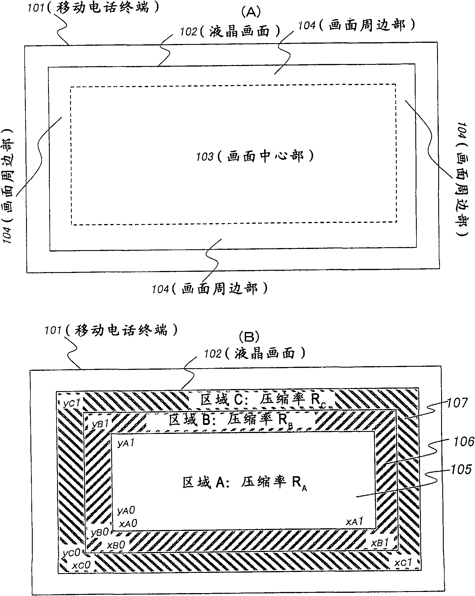
[0103] figure 1 It is a diagram explaining the area division of the screen of the liquid crystal display device according to the first embodiment of the present invention mounted on a mobile phone terminal.
[0104] figure 1 The mobile phone terminal 101 shown in (A) has a liquid crystal screen 102 . Here, the area near the center of the screen in the liquid crystal screen 102 is called the screen center 103 , and the area near the edge of the screen is called the screen peripheral 104 . For example, in the liquid crystal screen 102, the portion obtained by removing 10% of the vertical length at the upper and lower end portions and 10% of the horizontal length at the left and right end portions can be regarded as the screen center portion 103, and the A portion that is not the center portion 103 of the screen serves as the peripheral portion 104 of the screen. Here, the ratio of the lengths and the shapes of the central port...
no. 2 approach
[0179] Figure 8 It is a diagram explaining the area division of the screen of the liquid crystal display device according to the second embodiment of the present invention mounted on the mobile phone terminal.
[0180] Figure 8 The area division of the liquid crystal screen of the second embodiment shown in the figure 1 In addition to the three regions A ( 105 ), B ( 106 ), and C ( 107 ) of the liquid crystal screen in the first embodiment shown, a fourth region Z ( 108 ) is added. But when Figure 8 In the shown second embodiment, the overdrive process is omitted for the pixels to which the added fourth zone Z (108) belongs. That is, data compression by the image compression unit 2233 of the overdrive calculation unit 223, storage in the frame memory 224, and data expansion by the image expansion unit 2233 are omitted for pixels belonging to the fourth zone Z (108). As a result, the storage capacity of the frame memory 224 can be saved for the pixels in the outermost p...
no. 3 approach
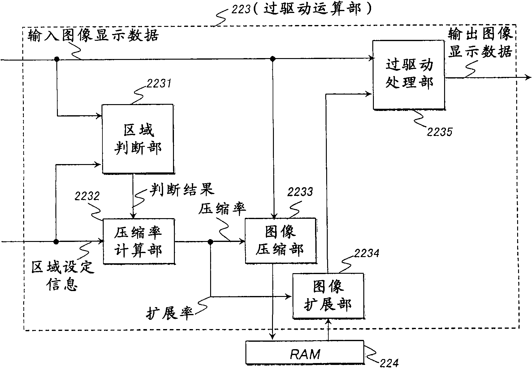
[0189] Figure 11 It is a diagram showing the configuration of the overdrive calculation unit 223 of the display driver 220 according to the third embodiment of the present invention.
[0190] Figure 11 The overdrive computing unit 223 of the third embodiment shown with Figure 9 The overdrive calculation unit 223 of the second embodiment shown is the same, including a region determination unit 2231 , a compression rate calculation unit 2232 , an image compression unit 2233 , an image expansion unit 2234 , an overdrive processing unit 2235 , and a multiplexer 2236 . But when Figure 11 In the third embodiment shown, an overdrive permission decision unit 2237 is further added to the overdrive calculation unit 223 . Moreover, in Figure 11 In the overdrive calculation unit 223 of the third embodiment shown, the overdrive permission determination unit 2237 is supplied with the area A ( 105 ), area B ( 106 ), and area C ( 107) The data compression ratio R A , R B , R C Th...
PUM
 Abstract
Description
Claims
Application Information
 - R&D
- Intellectual Property
- Life Sciences
- Materials
- Tech Scout
- Unparalleled Data Quality
- Higher Quality Content
- 60% Fewer Hallucinations
Browse by: Latest US Patents, China's latest patents, Technical Efficacy Thesaurus, Application Domain, Technology Topic, Popular Technical Reports.
© 2025 PatSnap. All rights reserved.Legal|Privacy policy|Modern Slavery Act Transparency Statement|Sitemap|About US| Contact US: help@patsnap.com


