Electric main shaft with mouse cage type motor stator cooling structure

A motor stator and cooling structure technology, which is applied to the functional parts of the main shaft and the field of electric spindles, can solve the problem that the coaxiality between the front bearing seat hole and the motor stator is difficult to ensure, the performance parameters affecting the rotation accuracy of the electric spindle, and the difficulty of disassembling and assembling the motor stator are increased. problems, to achieve the effects of compensating axial elastic thermal deformation, facilitating processing, and simplifying the cooling structure

Inactive Publication Date: 2012-07-25
HUNAN UNIV
View PDF0 Cites 2 Cited by
  • Summary
  • Abstract
  • Description
  • Claims
  • Application Information

AI Technical Summary

Problems solved by technology

However, due to the omission of the sealing water jacket, the disassembly and assembly of the motor stator is more difficult. For the convenience of pressing the motor stator into and out of the housing, the front bearing seat, the rear bearing seat and the motor housing must be made Separated so that the motor stator can be pressed into or out of the housing using ring sleeve tooling
[0005] But this structure brings another problem
The front bearing of the high-speed electric spindle is seriously heated under the action of processing load. In order to ensure its heat dissipation and prolong its service life, external forced cooling is also required. If the front bearing seat is separated from the motor housing, the cooling structure will Difficult to install, at the same time, the overall rigidity of the connection between the front bearing seat and the motor shell will decrease, and the coaxiality between the front bearing seat hole and the motor stator is also difficult to ensure during the disassembly process, which will directly affect the rotation of the electric spindle Accuracy and other main performance parameters

Method used


Image

  • Electric main shaft with mouse cage type motor stator cooling structure
  • Electric main shaft with mouse cage type motor stator cooling structure
  • Electric main shaft with mouse cage type motor stator cooling structure

Examples


Embodiment Construction

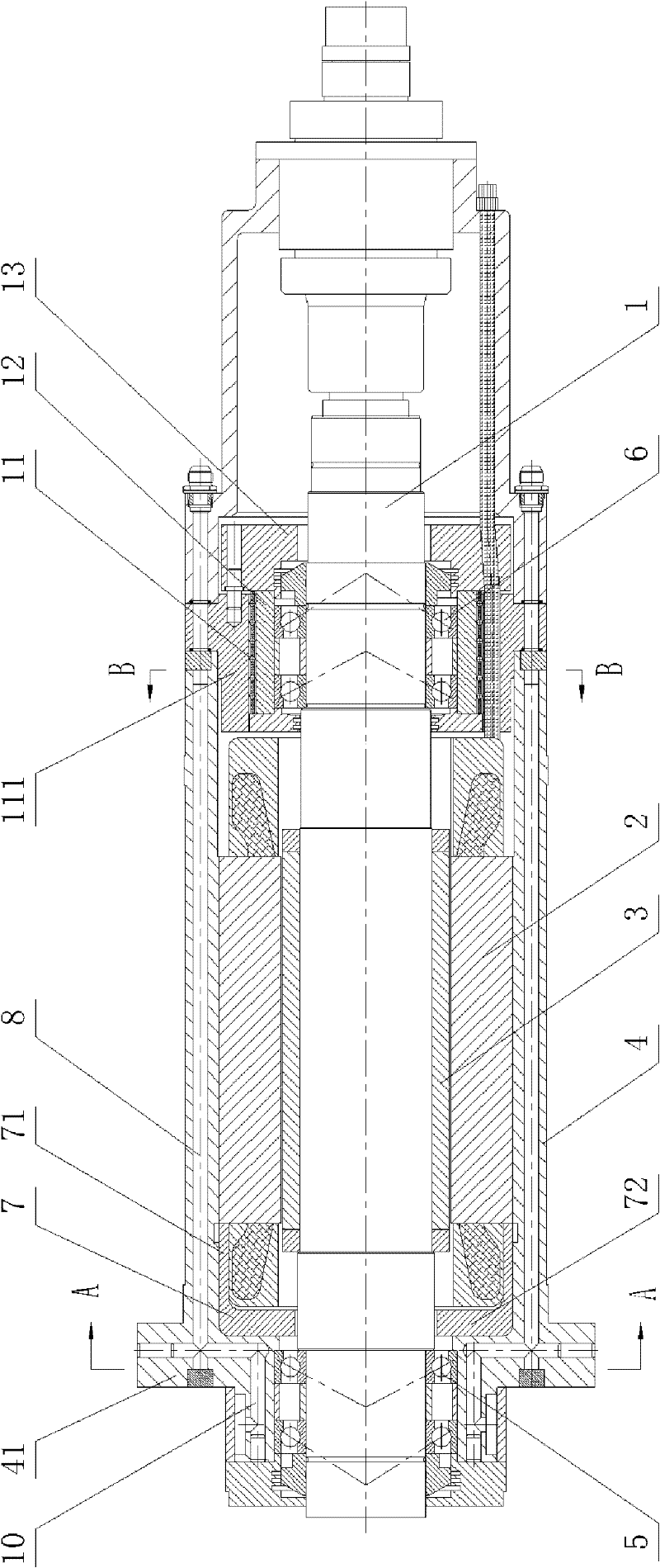
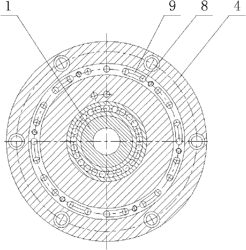
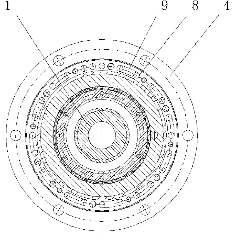
[0022] Figure 1 to Figure 4 It shows an embodiment of an electric spindle with a squirrel-cage motor stator cooling structure of the present invention, the electric spindle includes a spindle assembly 1, a motor stator 2, a motor rotor 3, a casing 4, a front bearing assembly 5 and a rear bearing Assembly 6, the motor stator 2 is set in the box body 4, the motor rotor 3 is set on the main shaft assembly 1, the main shaft assembly 1 is placed in the motor stator 2, and is supported by the front bearing assembly 5 and the rear bearing assembly 6 On the box body 4, a squirrel-cage cooling channel for cooling the motor stator 2 is provided on the box body 4. The front end of the box body 4 is provided with a front bearing seat 41 for installing the front bearing assembly 5, and the front bearing seat 41 and the box body 4 Casting as one body, which not only saves the sealing water jacket, reduces the radial dimension of the electric spindle, but also facilitates the coaxiality of ...


PUM


Abstract

The invention discloses an electric main shaft with a mouse cage type motor stator cooling structure, comprising a main shaft assembly, a motor stator, a motor rotor, a box body, a front bearing assembly and a rear bearing assembly, wherein the motor stator is sleeved in the box body; the motor rotor is sleeved on the main shaft assembly; the main shaft assembly is arranged in the motor stator and supported on the box body through the front bearing assembly and the rear bearing assembly; the box body is provided with a mouse cage type cooling passage used for cooling the motor stator; the front end of the box body is provided with a front bearing seat used for installing the front bearing assembly; the front bearing seat and the box body are cast into an integer; one end of the motor stator, which is close to the front bearing seat, is sleeved with a stator side ring, and the motor stator can act on the stator side ring from an inner hole of the front bearing seat through a cylinder tooling and be pushed out of the rear end of the box body. The electric main shaft with the mouse cage type motor stator cooling structure has compact structure, convenient disassembly and assembly andgood cooling effect.

Description

technical field [0001] The invention relates to a main shaft functional component of a high-speed machine tool in the field of mechanical manufacturing, in particular to an electric main shaft with a squirrel-cage motor stator cooling structure. Background technique [0002] High-speed precision machining, characterized by high cutting speed, high feed speed, and high machining accuracy, is one of the four contemporary advanced manufacturing technologies, and a high-tech that makes the second revolutionary leap in manufacturing technology after numerical control technology. . High-speed precision machining machine tools not only have extremely high production efficiency, but also can significantly improve the machining accuracy and surface quality of parts. The electric spindle of high-speed precision machine tools is the core functional component, and its performance directly affects the overall development level of high-speed precision machine tools. The electric spindle...

Claims


Application Information

Patent Timeline
Patent Type & Authority Patents(China)
IPC IPC(8): H02K7/08H02K5/16H02K9/197
Inventor 熊万里李芳芳吕浪纪宗辉
Owner HUNAN UNIV
Why Eureka
Try Eureka