Adhesive filling and grinding processing method for stator-rotor iron core component of motor

An iron core and grinding technology, applied in the manufacture of stator/rotor body, etc., can solve the problems of cracking length, out of tolerance, scrapping, etc., and achieve the effect of solving cracking, avoiding intermittent cutting, and good cooling conditions

Inactive Publication Date: 2010-11-24
FLIGHT AUTOMATIC CONTROL RES INST
View PDF3 Cites 18 Cited by
  • Summary
  • Abstract
  • Description
  • Claims
  • Application Information

AI Technical Summary

Problems solved by technology

[0008] The purpose of the present invention: to invent a glue-filled grinding method for the stator and rotor core assembly, so as to solve the problem of back teeth, cracks and length problems when the stator and rotor core assembly processing technology processes slender teeth and long iron core assemblies. Problems such as out-of-tolerance and scrapping caused by swelling and elongation

Method used


Image

  • Adhesive filling and grinding processing method for stator-rotor iron core component of motor
  • Adhesive filling and grinding processing method for stator-rotor iron core component of motor
  • Adhesive filling and grinding processing method for stator-rotor iron core component of motor

Examples


Embodiment Construction

[0027] Below in conjunction with accompanying drawing and embodiment the present invention is described in further detail:

[0028] The glue filling grinding process of the motor stator and rotor core assembly, the processing steps are as follows:

[0029] (1) The laminations are glued, and the armature punching sheets are bonded and laminated to form an iron core assembly;

[0030] (2) Fitter: grind the two ends of the iron core assembly to ensure the parallelism of the end faces;

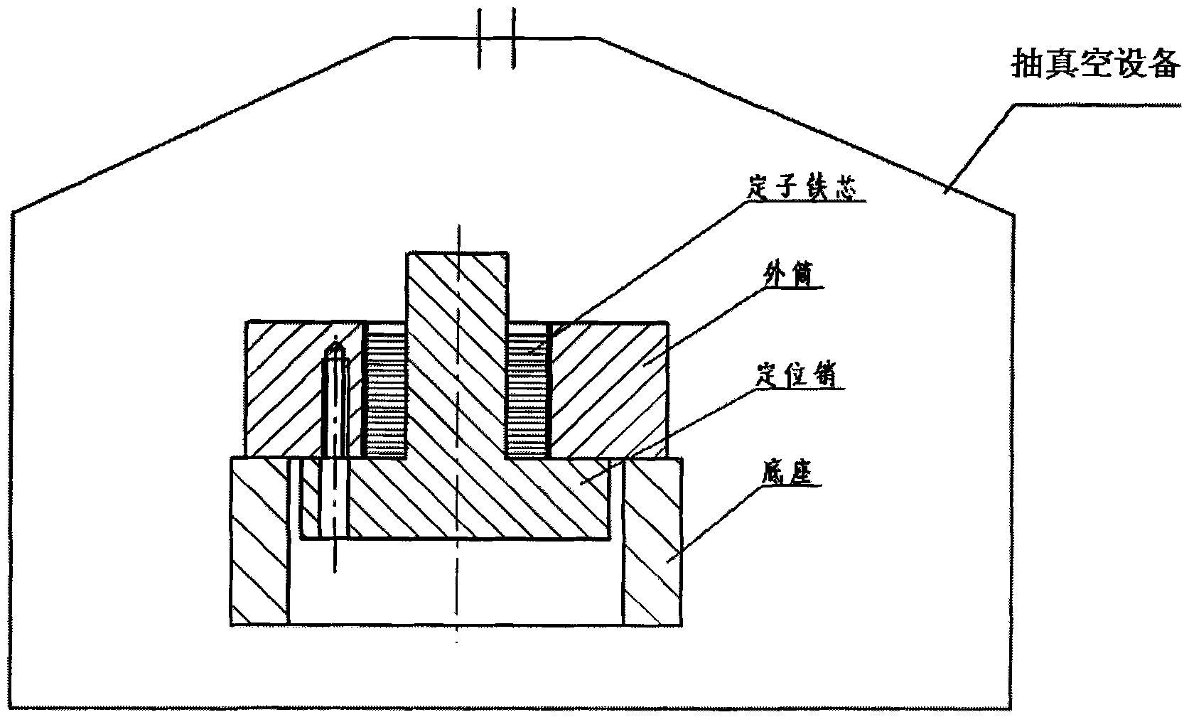
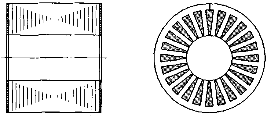
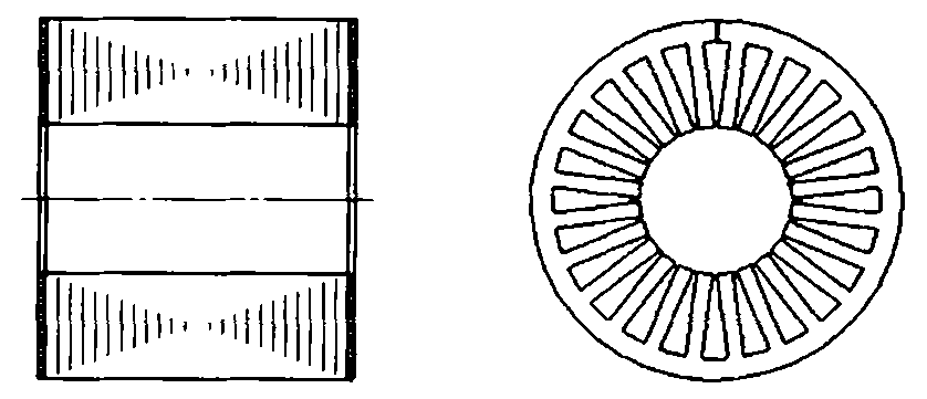
[0031] (3) Glue filling: Fill the colloid in the iron core groove by vacuum, see figure 1 with figure 2 , this step is the key to the whole process:

[0032] a) Mold loading: the mold is composed of an outer cylinder, positioning pins, base, and connecting screws, and the iron core assembly is placed on the positioning pins;

[0033] b) Preheating the mold: put the mold with iron core in an oven at 120°C to 130°C to preheat for 0.5 to 2 hours;

[0034] c) Potting: Put the potting compound in...


PUM

PropertyMeasurementUnit
thicknessaaaaaaaaaa

Abstract

The invention discloses an adhesive filling and grinding method for a stator-rotor iron core component of a motor. The method comprises the processes of gluing the iron core component through lamination, grinding an iron core by a benchwork, filling an adhesive, removing adhesive layers on two end faces by the benchwork, grinding an inner hole and an excircle of the iron core by a grinder, removing a potting adhesive and the like. The method is characterized in that: when the adhesive is filled, the potting adhesive is placed into a container, stirred and heated to a temperature of between 120 and 130 DEG C; the potting adhesive is poured into an pre-heated iron core groove immediately; a die is vacuumized in a vacuum chamber, so that bubbles are removed from the die, wherein the vacuum degree is 10 to 300Pa and the time is 5 to 20 minutes; and the die is taken out and cooled at the room temperature, so that the potting adhesive is solidified. Compared with the prior art, a profiled groove part of the stator-rotor iron core component forms an entity through the adhesive filling process so that deformation resistance of the stator-rotor iron core component is enhanced and interrupted cut is avoided; and at the same time, the grinding process solves the problems of crack, swelling, poor coaxiality and the like caused by internal and external conicity of the stator-rotor iron core component and temperature distortion of the adhesive layers of the iron core component.

Description

technical field [0001] The invention belongs to the field of motor manufacturing, and in particular relates to a processing technology of a motor stator and rotor iron core assembly. Background technique [0002] Micro motors are widely used in the field of industrial control, and their stator and rotor core components are usually made of multiple thin armature punches and glued together. There are multiple teeth and slots on the inner side of the stator punching sheet and on the outer side of the rotor punching sheet, which are used to place the field winding and the armature winding respectively. Increasing the tooth height and tooth width ratio of the stator and rotor cores and the length of the iron core is an important means to increase the output torque of the micro motor. In some typical high torque micro motor products, the thickness of the iron core reaches 75mm, and the teeth of the punching sheet The height and tooth width ratio reached 11:1. [0003] The increa...

Claims


Application Information

Patent Timeline
Patent Type & Authority Applications(China)
IPC IPC(8): H02K15/02
Inventor 史爱兰王以平黄涛
Owner FLIGHT AUTOMATIC CONTROL RES INST
Why Eureka
Try Eureka