
Process and apparatus for producing fluorinated gaseous compound

A manufacturing method and compound technology, applied in the direction of nitrogen compounds, interhalogen compounds, chemical instruments and methods, etc., can solve the problems of increasing the capacity of the reactor 22, and achieve the effect of less risk of failure and simple equipment

Inactive Publication Date: 2012-10-10
CENT GLASS CO LTD
View PDF4 Cites 0 Cited by
  • Summary
  • Abstract
  • Description
  • Claims
  • Application Information

AI Technical Summary

Problems solved by technology

[0017] In the case where the process described in Patent Document 4 is applied to the method for producing fluorinated gas compounds, since the reaction tank 22 of Patent Document 4 is not linear as in the present invention, but pot-shaped, when increasing On a production scale, the capacity of the reactor 22 has to be increased, and the same problem as in Patent Document 2 exists.

Method used


Image

  • Process and apparatus for producing fluorinated gaseous compound
  • Process and apparatus for producing fluorinated gaseous compound
  • Process and apparatus for producing fluorinated gaseous compound

Examples


Embodiment 1

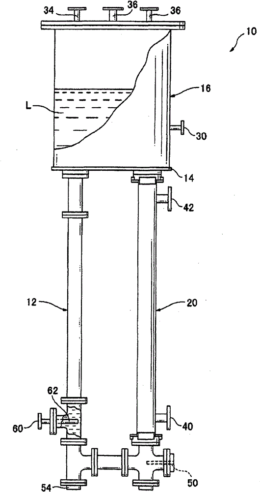
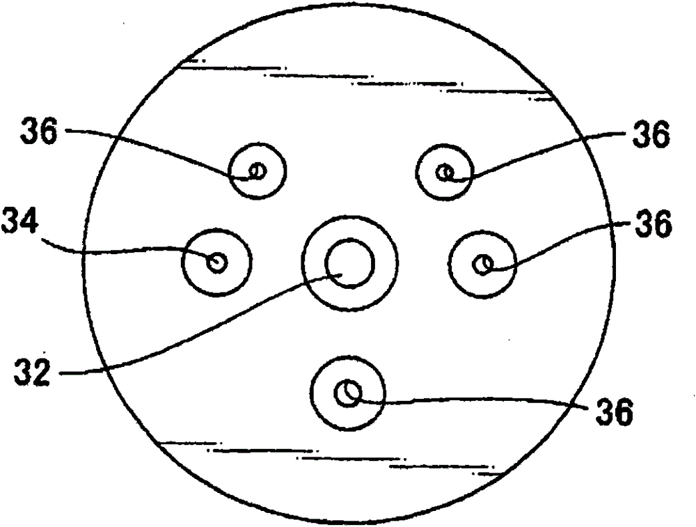
[0064] ready to have figure 1 The structure of the fluorinated gas compound plant 10 is shown as a reaction plant. The raw material liquid L (NH 4F·2.0HF), the raw material liquid L is introduced into the reaction device until the height of the separation layer 16 is roughly in the middle. The amount of the introduced raw material liquid is about 35L. During the reaction, the reduced amount of the raw material liquid L is appropriately replenished from the reaction liquid replenishment port 54 .

[0065] From the raw material supply port 60, the raw material gas CLF is introduced at a flow rate of 4SLM 3 , the reaction is started, and the reaction gas NF obtained by the reaction is taken out from the gas outlet 36 2 Cl, NFCl 2 , a part of which passes through a pipe (made of SUS304) not shown in the figure, and returns to the raw material supply port 60 . The flow rate of the reaction product gas introduced from the raw material supply port 60 is 40 to 60 SLM.

[0066] ...

Embodiment 2

[0069] ready to have figure 1 The structure of the fluorinated gas compound plant 10 is shown as a reaction plant. The raw material liquid L (NH 4 F·2.0HF), the raw material liquid L is introduced into the reaction device until the height of the separation layer 16 is roughly in the middle. The amount of the introduced raw material liquid is about 35L. During the reaction, the reduced amount of the raw material liquid L is appropriately replenished from the reaction liquid replenishment port 54 .

[0070] From the raw material supply port 60, introduce raw material gas ClF at a flow rate of 0.4SLM 3 , the reaction is started, and the reaction gas NF obtained by the reaction is taken out from the gas outlet 36 2 Cl, NFCl 2 , so that its entire amount passes through the subsequent reaction to form "the gaseous compound NF obtained by further fluorination 3 ”, let a part of the obtained gas compound pass through a pipe (made of SUS304) not shown in the figure, and return to...


PUM


Abstract

An apparatus for producing a fluorinated gaseous compound. The apparatus includes a circulation system which comprises: a reaction zone in which a liquid mixture containing a raw-material liquid is reacted with a raw-material gas; a flow zone in which only the liquid mixture flows; an upper transfer zone in which the liquid mixture which has undergone the reaction is transferred from an upper part of the reaction zone to an upper part of the flow zone; and a lower transfer zone in which the liquid mixture is transferred from a lower part of the flow zone to a lower part of the reaction zone. (A) The raw-material gas is introduced into the lower part of the reaction zone, and (B) at least one fluorinated gaseous compound selected between a first fluorinated gaseous compound which is a reaction product yielded in the reaction zone and a second fluorinated gaseous compound obtained by further fluorinating the first fluorinated gaseous compound is introduced into the lower part of the reaction zone. The liquid mixture is circulated by these operations (A) and (B).

Description

technical field [0001] Fluorinated gaseous compounds, e.g. NF 3 , IF 5 , IF 7 、CIF 3 , WF 6 It is used as an internal cleaning agent for semiconductor manufacturing equipment such as CVD equipment and PVD equipment. Various studies have been conducted on methods for efficiently producing these gaseous compounds. In addition, the aforementioned NF 3 , IF 5 , IF 7 、CIF 3 , WF 6 , is a substance in which the fluorination reaction mentioned as an example in the present invention proceeds completely. Background technique [0002] For example, the applicant proposed to make the liquid ammonium complex and the gaseous CIF 3 Reaction of interhalogen compounds such as, synthetic formula NF x L 3-x (L is a halogen other than F, and 1≤x≤3) represents a gaseous nitrogen halide method (see Patent Document 1). The nitrogen halide is further fluorinated in the following process and converted into NF 3 . In order to efficiently produce gaseous fluorinated compounds, it is pr...

Claims


Application Information

Patent Timeline
Patent Type & Authority Patents(China)
IPC IPC(8): C01B21/083C01B7/24
CPCC01B7/24C01B21/0835C01B21/0832
Inventor 田中久雄毛利勇田仲健二
Owner CENT GLASS CO LTD
Learn More