Thermo roll

A technology of heated and heat transfer agent, used in textiles and papermaking, calendering, papermaking, etc., can solve the problems of high cost of powder metallurgy technology and few suppliers of large parts, avoid streaks, machining operations Simple, low-volume effects

Active Publication Date: 2010-11-24
VALMET TECH OY
View PDF8 Cites 4 Cited by
  • Summary
  • Abstract
  • Description
  • Claims
  • Application Information

AI Technical Summary

Problems solved by technology

However, powder metallurgy manufacturing technology

Method used


Image

  • Thermo roll
  • Thermo roll
  • Thermo roll

Examples


Embodiment Construction

[0036] In the following description, the same reference numerals refer to the same components. It should be noted that the drawings are not drawn to scale in all cases and that they mainly serve the purpose of illustrating embodiments of the invention.

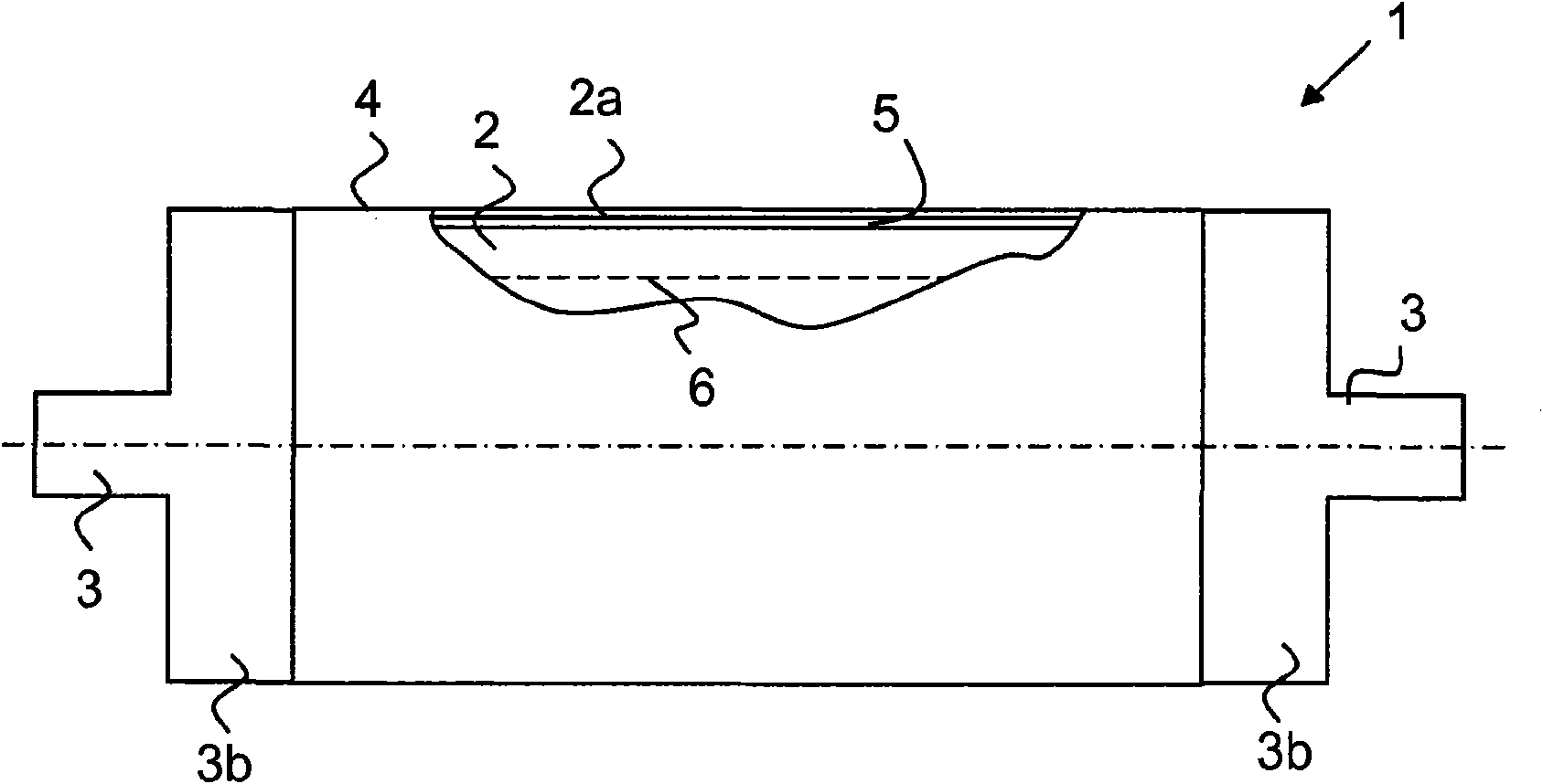
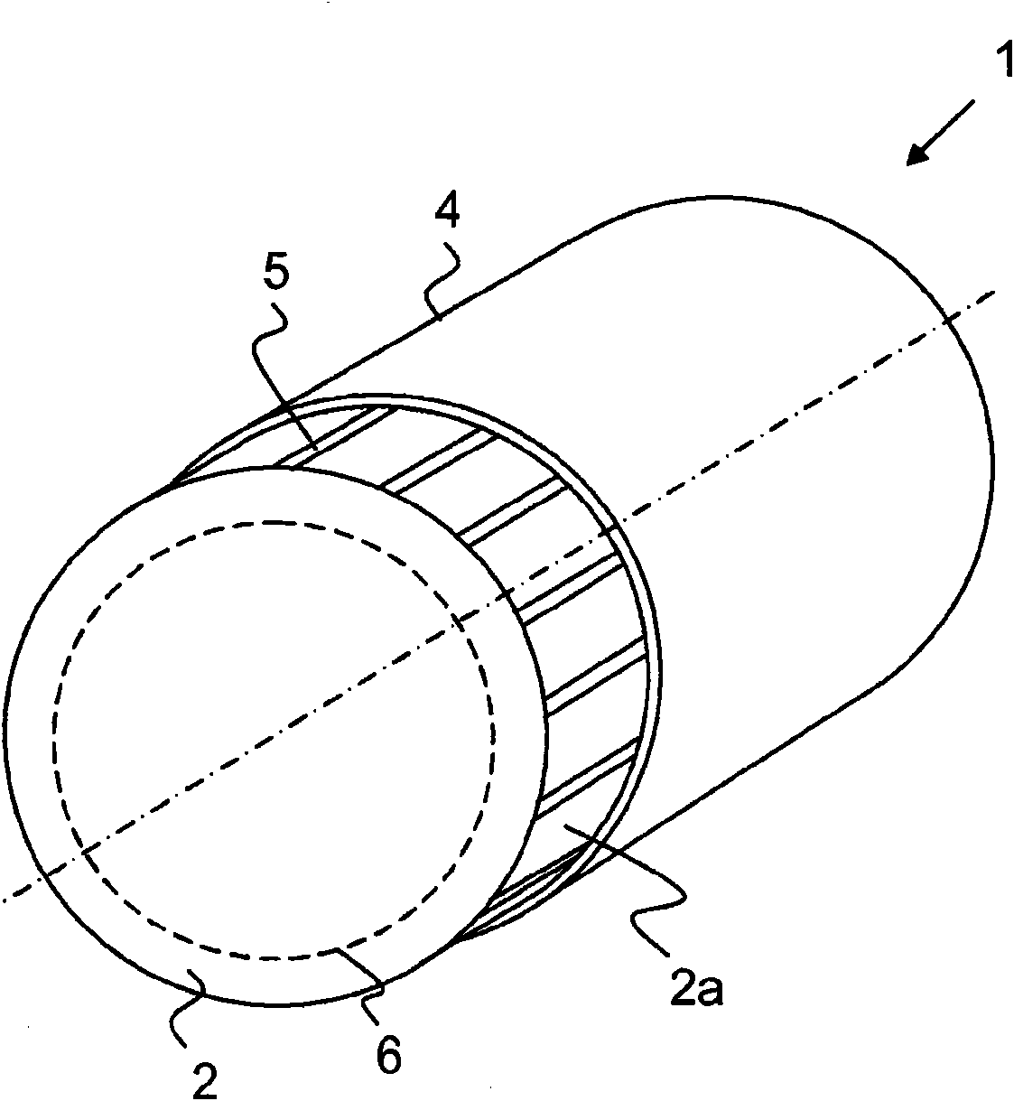
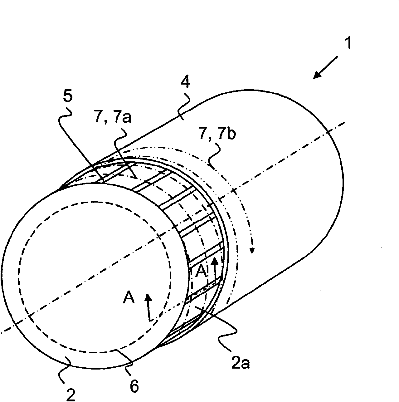
[0037] figure 1 and figure 2 Shows a heated and / or cooled roll according to an embodiment of the invention, namely a thermo roll 1 provided with a thin outer layer 4, for example of steel, and an inner shaft 2 inside the outer layer, the inner The surface of the shaft 2 has flow grooves for constituting flow channels 5 for the heat transfer agent.

[0038] The heat roller 1 includes an inner shaft 2 and a shaft end 3; the shaft end 3 is fastened to the end of the inner shaft 2 to carry a load. exist figure 1 In the example shown, at least one shaft end 3 fastened to the inner shaft 2 comprises at least one flow channel for introducing and / or leading out a heat transfer medium. The thermo roll 1 preferably comprises an ...


PUM

PropertyMeasurementUnit
Surface hardnessaaaaaaaaaa

Abstract

A heated and/or cooled roll, i.e., a thermo roll (1), of a fiber web machine comprises a cylindrical inner shaft (2) for carrying a load, a metallic outer layer (4) surrounding the inner shaft, and flow channels (5) for a heat-transfer agent, arranged in connection with an interface between the inner shaft and the outer layer. The thermo roll (1) is manufactured by assembling the inner shaft (2) and the outer layer (4). The flow channels (5) of the thermo roll consist of flow grooves (5) formed before the assembly of the inner shaft and the outer layer on an outer surface (2a) of the inner shaft (2) and/or an inner surface of the outer layer (4).

Description

technical field [0001] The invention relates to a thermo roll for use in a fiber web machine, preferably a paper machine, a board machine and a chemical pulp machine, for processing (eg heating, calendering, wet pressing and / or cooling) web-like material . [0002] The invention relates to heated and / or cooled rolls, ie thermo rolls, comprising a cylindrical inner shaft for carrying a load, a metal outer layer surrounding the inner shaft, and a heat-transfer agent A flow channel is provided in association with the interface between the inner shaft and the outer layer. Background technique [0003] Currently, the thermal energy required for calendering paper and board is generated by heated rolls (ie thermo rolls). Calender operating speeds have increased significantly over the past few years. In order to obtain the desired calendering effect, the surface temperature of the hot roller must also be increased to 200°C-250°C or even higher. The high operating speed combined ...

Claims


Application Information

Patent Timeline
IPC IPC(8): D21G1/02
CPCD21G1/0246D21G1/0266D21F3/08F16C13/00
Inventor 亚尼·哈科拉米卡·维尔扬马阿马斯·格特汤米·万哈拉
Owner VALMET TECH OY
Why Eureka
Try Eureka