Exhaust gas recirculation cooling element for an internal combustion engine

A technology of exhaust gas recirculation and cooler, applied in the direction of internal combustion piston engine, combustion engine, heat exchanger, etc., can solve the problems of insufficient efficiency and achieve the effects of compact structure, extended inspection and maintenance intervals, and high efficiency

Active Publication Date: 2010-11-24
GEA机械冷却技术有限公司
View PDF0 Cites 17 Cited by
  • Summary
  • Abstract
  • Description
  • Claims
  • Application Information

AI Technical Summary

Problems solved by technology

This lack of efficiency manifests itself especially in exhaust gas recirculation coolers for larger internal combustion engines

Method used


Image

  • Exhaust gas recirculation cooling element for an internal combustion engine
  • Exhaust gas recirculation cooling element for an internal combustion engine
  • Exhaust gas recirculation cooling element for an internal combustion engine

Examples


Embodiment Construction

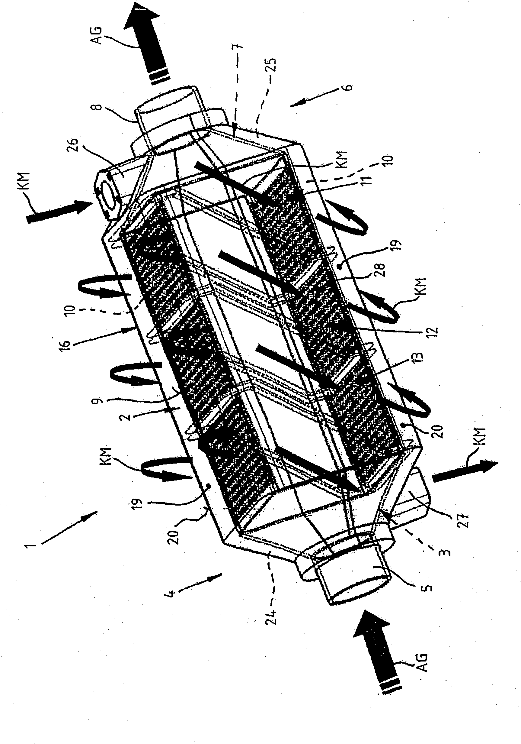
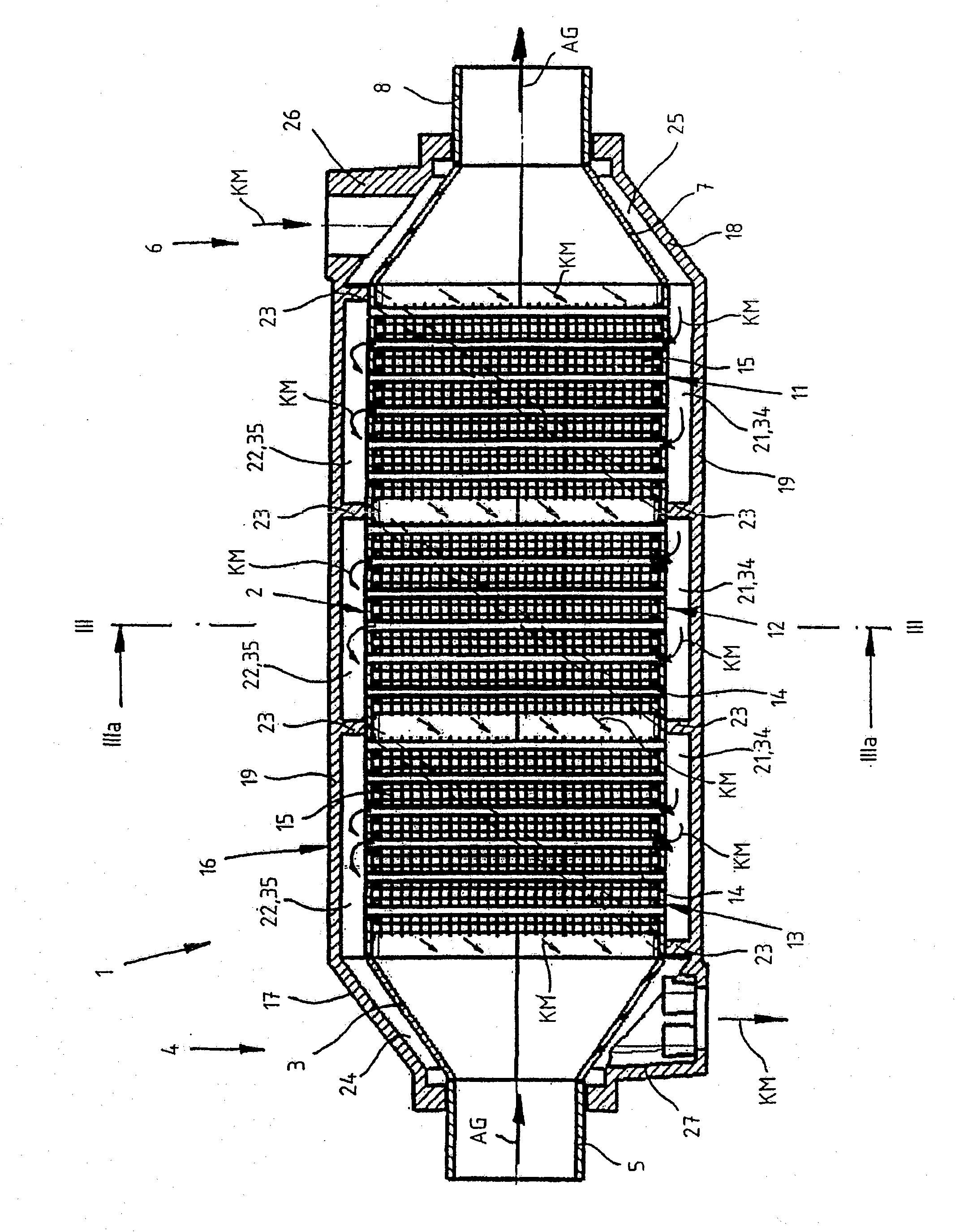
[0030] exist Figures 1 to 3 Indicated by 1 is an exhaust gas recirculation cooler for a large internal combustion engine not shown in detail, such as can be used, for example, on board a ship. In the exhaust gas recirculation cooler 1 , the hot exhaust gas AG leaving the internal combustion engine undergoes an indirect heat exchange with a coolant KM in the form of cooling water.

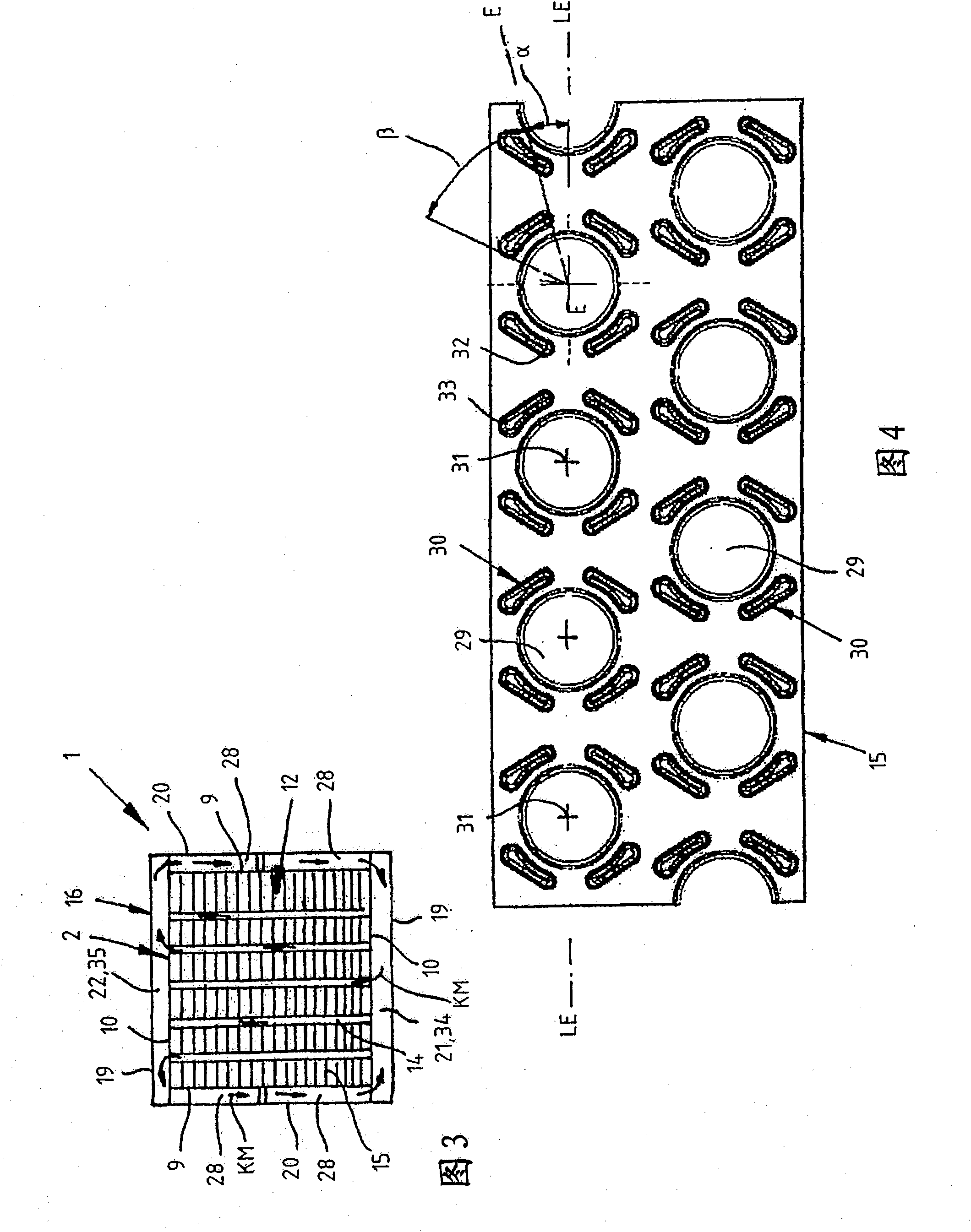
[0031] The exhaust gas recirculation cooler 1 has a heat exchange insert 2 that is rectangular in cross section and has a conical inlet region 3 for hot exhaust gas AG at one end 4 . The inflow region 3 is located downstream of the inflow connection 5 for the hot exhaust gas AG. At the other end 6 of the exhaust gas recooler 1 there is a conical outflow region 7 of the heat exchange insert 2 for the cooled exhaust gas AG. The outflow region 7 merges into a cylindrical outlet connection 8 for the cooled exhaust gas AG.

[0032]The heat exchange insert 2 has two closed side walls 9 facing each oth...


PUM


Abstract

The invention relates to an exhaust gas recirculation cooling element (1) comprising a heat exchanger (2) having several heat exchange units (11, 12, 13) that are introduced between the inflow region (3) and the outflow region (7) of the exhaust gas (AG). Said units comprise cooling tubes with cooling ribs. The heat exchanger (2) is surrounded by a housing (16), the lateral walls thereof (19) being arranged at a distance in relation to the perforated lateral walls (10). Guide channels (28) are arranged between the closed lateral walls (9) of the heat exchanger (2) and the adjacent lateral walls (20) of the housing (16), said guide channels extending in a diagonal manner and being provided to direct the coolant (KM) from a coolant inlet to the coolant outflow through the individual heat exchange units (11, 12, 13).

Description

technical field [0001] The invention relates to an exhaust gas recirculation cooler for an internal combustion engine according to the features of claim 1 . Background technique [0002] Exhaust gas return coolers are well known for use in the motor vehicle sector. Such exhaust gas recirculation coolers themselves suffer from insufficient efficiency. This is primarily based on an unsatisfactory area ratio of the cooling water side to the exhaust gas side of the order of 1:1. This lack of efficiency manifests itself particularly in exhaust gas recirculation coolers for larger internal combustion engines. The larger internal combustion engines are to be understood as internal combustion engines which are used, for example, on ships in the marine sector or in very heavy construction vehicles. The exhaust gas recirculation coolers used here require a completely different performance than exhaust gas recirculation coolers used in the motor vehicle sector in connection with sig...

Claims


Application Information

Patent Timeline
Patent Type & Authority Applications(China)
IPC IPC(8): F28D7/16F28F9/26
CPCF28F1/32F28D21/0003F28F9/26F28D7/1623F28D7/163Y02T10/12
Inventor M·洛布雷耶尔D·克劳斯D·阿本德罗特
Owner GEA机械冷却技术有限公司
Why Eureka
Try Eureka