Electropneumatic transducer with a pneumatic pressure-regulating valve

A technology of pressure regulation and converter, which is applied in the direction of physical quantity changer, auxiliary non-electric fluid pressure control, mechanical equipment, etc., which can solve the problems of high manufacturing cost and large installation space

Inactive Publication Date: 2010-12-01
ABB TECH AG
View PDF11 Cites 2 Cited by
  • Summary
  • Abstract
  • Description
  • Claims
  • Application Information

AI Technical Summary

Problems solved by technology

[0009] Disadvantages of the known electropneumatic converters consisting of a pressure regulator and a separate electrically activated pressure control component are high manufacturing costs and a large installation space, which is counter to miniaturization

Method used


Image

  • Electropneumatic transducer with a pneumatic pressure-regulating valve
  • Electropneumatic transducer with a pneumatic pressure-regulating valve
  • Electropneumatic transducer with a pneumatic pressure-regulating valve

Examples


Embodiment Construction

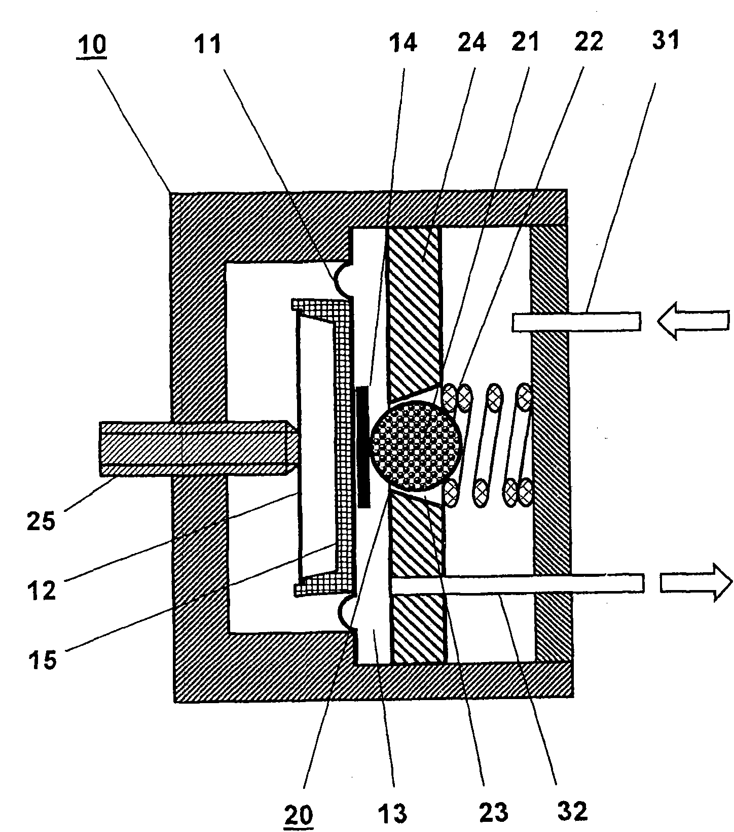
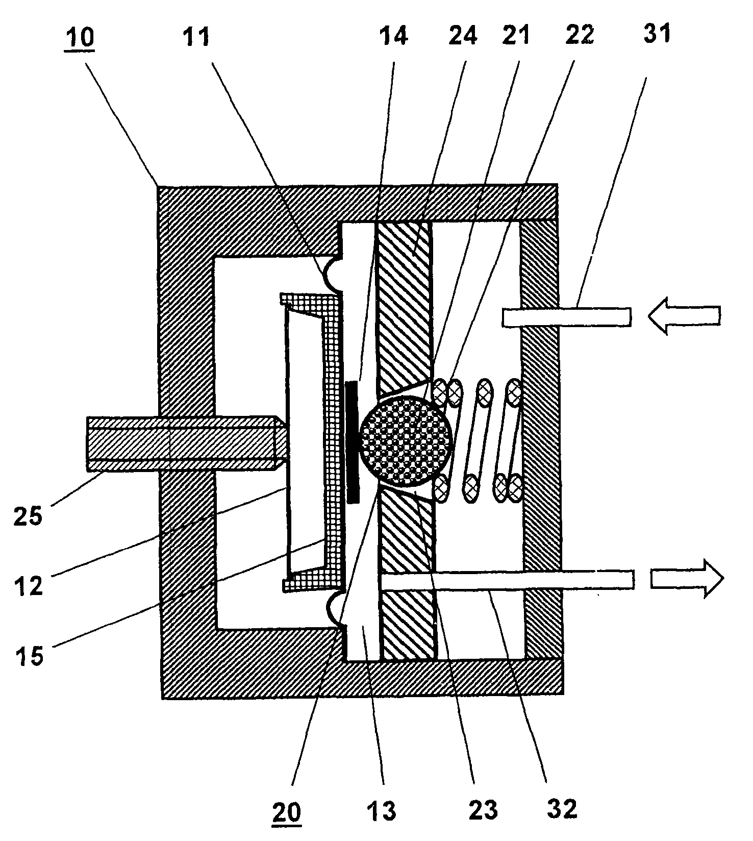
[0022] figure 1 is a cross-sectional view of the electropneumatic converter 10 with a pneumatic pressure regulating valve. The pressure regulating valve has a pressure chamber 13 which is closed off by a regulating diaphragm 11 and a housing wall 24 opposite the regulating diaphragm.

[0023] Arranged in the housing wall 24 is a control valve 20 which consists of a dimensionally stable ball 21 which is loaded by a spring 22 and which is situated in a conical bore 23 which narrows in the direction of the regulating diaphragm 11 . Unregulated pressure medium 31 is fed towards the side of the ball 21 facing the spring 22 .

[0024] The adjusting diaphragm 11 is supported in a non-positive manner on a pressure plate 15 which is connected to a rotationally symmetrical adjusting spring 12 . The center of gravity of the adjustment spring 12 is supported on the adjustment screw 25 .

[0025] According to a first embodiment of the invention, the pressure plate 15 is designed as an a...


PUM


Abstract

An electropneumatic transducer is disclosed having a pneumatic pressure-regulating valve for regulating a control pressure in a pressure chamber by a regulator diaphragm, which rests on (e.g., against a counter-bearing). The counter-bearing can include at least one pressure disk, a regulator spring and an adjusting screw, the regulator diaphragm being held in force equilibrium by the regulator spring and the control pressure. The regulator diaphragm can be coupled to a control valve such that the control valve opens or closes as a function of actual control pressure. The counter-bearing can include an electrically drivable actuator.

Description

technical field [0001] The invention relates to an electropneumatic converter with a pneumatic pressure regulating valve for regulating a control pressure by means of an adjusting diaphragm which is force-balanced by a reference part and the control pressure. Background technique [0002] Such pneumatic electropneumatic (elektropneumatisch) converters are generally known and are used to convert electrical signals into pneumatic signals. In this case, the pressure of the control air is varied by means of the nozzle-flapper system as a function of electrical signals. For this purpose, the control air is first regulated to a constant pressure via a pressure regulator. Next, the control air flows through the nozzles towards the baffle. By adjusting the distance between the baffle and the nozzle, the flow rate can be changed, and the control pressure (differential pressure) can also be changed. [0003] The pressure control valves required for this are generally known and are ...

Claims


Application Information

Patent Timeline
Patent Type & Authority Applications(China)
IPC IPC(8): F15B5/00G05D16/14
CPCF15B5/006
Inventor H·穆勒
Owner ABB TECH AG
Why Eureka
Try Eureka