Solar energy photovoltaic device of vacuum glass tube and method

A vacuum glass tube and solar photovoltaic technology, applied in photovoltaic power generation, photovoltaic thermoelectric hybrid power generation, light radiation generators, etc., can solve the problems of not being able to provide point energy and heat energy at the same time, without further steps, and the efficiency of battery power generation is reduced, so as to increase The effect of comprehensive utilization efficiency, improvement of application efficiency and cost reduction

Inactive Publication Date: 2010-12-01
BEIJING WISWORD HI TECH
View PDF4 Cites 9 Cited by
  • Summary
  • Abstract
  • Description
  • Claims
  • Application Information

AI Technical Summary

Problems solved by technology

[0007] However, in the existing solar photoelectric conversion cells, solar photoelectric conversion materials are processed on a substrate material, and glass and other packaging are added to the outside. At the same time, since there is no further temperature control device, the photovoltaic cells are affected by temperature during use. , the power generation efficiency of the usual battery at noon is actually reduced. If the temperature control device is added, the cost of the solar panel will be increased, and the comprehensive utilization of photovoltaic light and heat will not be realized at the same time. Energy and thermal energy, affecting the comprehensive utilization efficiency of solar energy

Method used


Image

  • Solar energy photovoltaic device of vacuum glass tube and method
  • Solar energy photovoltaic device of vacuum glass tube and method
  • Solar energy photovoltaic device of vacuum glass tube and method

Examples


Embodiment 1

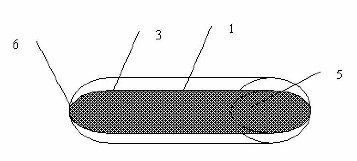
[0068] Example 1: Solar Photoelectric Converter with Inner Coating of Vacuum Glass Tube

[0069] according to figure 1 As shown, the outer surface of the inner casing of the vacuum layer of the vacuum glass tube is processed with a solar photoelectric coating (3). layers to convert solar energy into electricity.

[0070] The device can be used directly, or a fluid can be arranged through the open end (5), and the fluid transfers the heat energy inside the vacuum glass tube to the outside, so as to realize the temperature control of the device and the collection of heat energy.

Embodiment 2

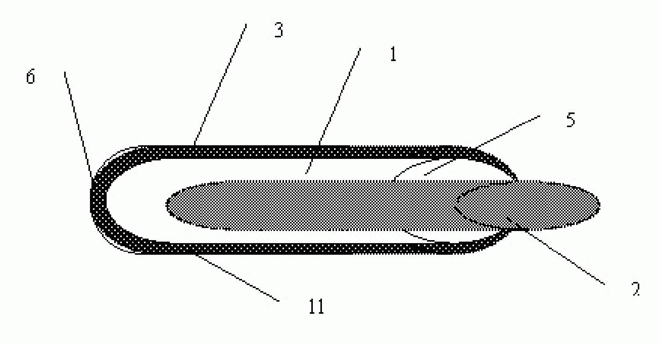
[0071] Example 2: Solar Photoelectric Converter with Vacuum Glass Tube Outer Coating

[0072] according to figure 2 As shown, the inner surface of the outer housing of the vacuum layer of the vacuum glass tube is processed with a solar photoelectric coating (3). layers to convert solar energy into electricity.

[0073] The evaporation end of the heat pipe (2) is set inside the cavity of the vacuum glass tube, the heat pipe is connected to the vacuum glass tube through the connection structure (4), and the condensation end is set outside the vacuum glass tube; for low temperature applications, non-tracking can be used For medium temperature applications, trough line focused solar collection can be used, for high temperature applications, butterfly or tower solar tracking technology can be used; so for any required working temperature, vacuum glass tubes can be used The conversion of solar energy into electrical energy is realized, and the sampling heat pipe realizes temperat...

Embodiment 3

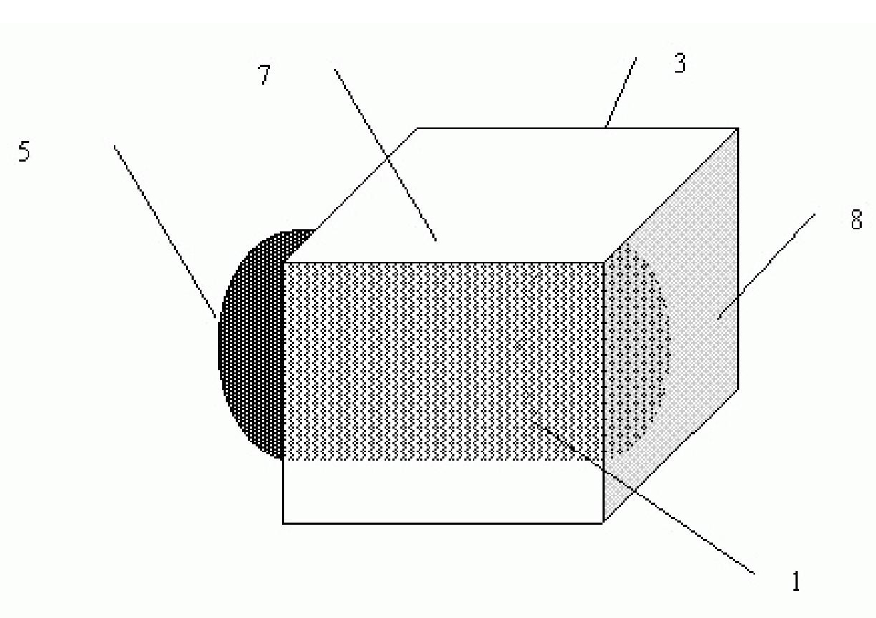
[0074] Example Three: Hexagonal Vacuum Glass Tube Photoelectric Converter

[0075] according to image 3 Shown, be also provided with hexagonal outer cavity (7) outside the vacuum glass tube (1) of cylindrical body, be provided with solar lens (8) at the sun light incidence position of vacuum glass tube, on the vacuum glass tube The heat exchanger (2) is a stainless steel cylindrical device, and a coating for converting solar energy into electric energy is arranged on the vacuum layer of the vacuum glass tube, and the silicon layer on the glass substrate is characterized by a p+ layer: 10 mm to 40 mm thick, Resistivity 2~3?0-8 ohm cm; p layer: 8 Ω~10 Ω, resistivity: 0.2~2 ohm cm; n+ layer: 0.2 Ω~0.4 Ω thick, resistivity 1~2?0-3 ohm cm; the glass substrate is divided into 3cm? Multiple regions of cm.

[0076] The heat exchange device is set inside the vacuum glass tube, and the heat exchange device is provided with an inlet (5) and an outlet (5). The fluid enters from the in...


PUM


Abstract

The invention aims to provide a solar energy photovoltaic device of a vacuum glass tube. Solar energy optical to electrical material is arranged and processed in the vacuum layer of the vacuum glass tube to convert solar energy into electric energy; after the vacuum glass tube is sealed, the vacuum glass tube can be directly used and does not need to be packaged so as to lower the cost of the existing optical to electrical material; meanwhile, fluid or a heat pipe can be arranged in the cavity of a vacuum glass tube transmitting device to control the temperature of the solar energy optical to electrical material, so that the solar energy optical to electrical material can always keep high-efficiency conversion effect, and heat energy is comprehensively utilized after being transferred by the fluid or the heat pipe, and thus, solar energy generation and temperature control are realized, solar energy conversion efficiency is improved, and solar energy heat is comprehensively and integrally utilized. In order to improve solar energy utilization efficiency, a solar energy mirror is arranged out of the device to focus solar energy, i.e. reflect, refract, project solar energy, and in order to reduce heat waste, an insulating layer is added out of the device.

Description

technical field [0001] The invention relates to the utilization of solar energy, a device for converting solar energy into electric energy, in particular to sampling vacuum glass tubes for solar photovoltaic power generation and comprehensive utilization of light and heat. Background technique [0002] The mature application technology of solar energy is the low-temperature hot water utilization of solar energy. The vacuum glass tube technology is mainly used to convert solar energy into heat energy. In this technology, there is a technology of inserting a heat pipe into the vacuum glass tube to transfer heat to the outside to obtain solar energy. , and various devices developed on the basis of vacuum glass, in which a vacuum layer is set in the vacuum glass tube for heat preservation, and a selective coating is set inside the vacuum layer to absorb and convert solar energy, although the vacuum glass layer is very Good heat preservation has been realized, and the selective c...

Claims


Application Information

Patent Timeline
Patent Type & Authority Applications(China)
IPC IPC(8): H02N6/00H01L31/058H01L31/052H02S40/22H02S40/42H02S40/44
CPCY02E10/60Y02E10/52Y02E10/50
Inventor 李建民
Owner BEIJING WISWORD HI TECH
Why Eureka
Try Eureka