Particulate filtration device

A filter device and particle technology, applied in the direction of dispersed particle filtration, membrane filter, noise reduction device, etc., can solve the problem of poor regeneration process of the filter, and achieve the effect of simple and compact filter design

Inactive Publication Date: 2010-12-01
VOLVO TECH +1
View PDF9 Cites 2 Cited by
  • Summary
  • Abstract
  • Description
  • Claims
  • Application Information

AI Technical Summary

Problems solved by technology

Such local temperature maxima may be caused by irregular soot collection, or by poor regeneration of the filter

Method used


Image

  • Particulate filtration device
  • Particulate filtration device
  • Particulate filtration device

Examples


Embodiment Construction

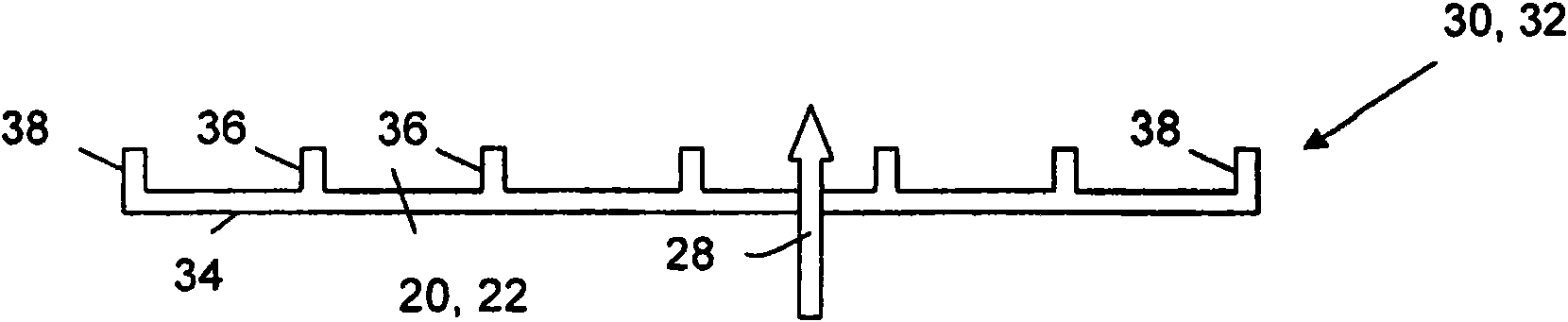
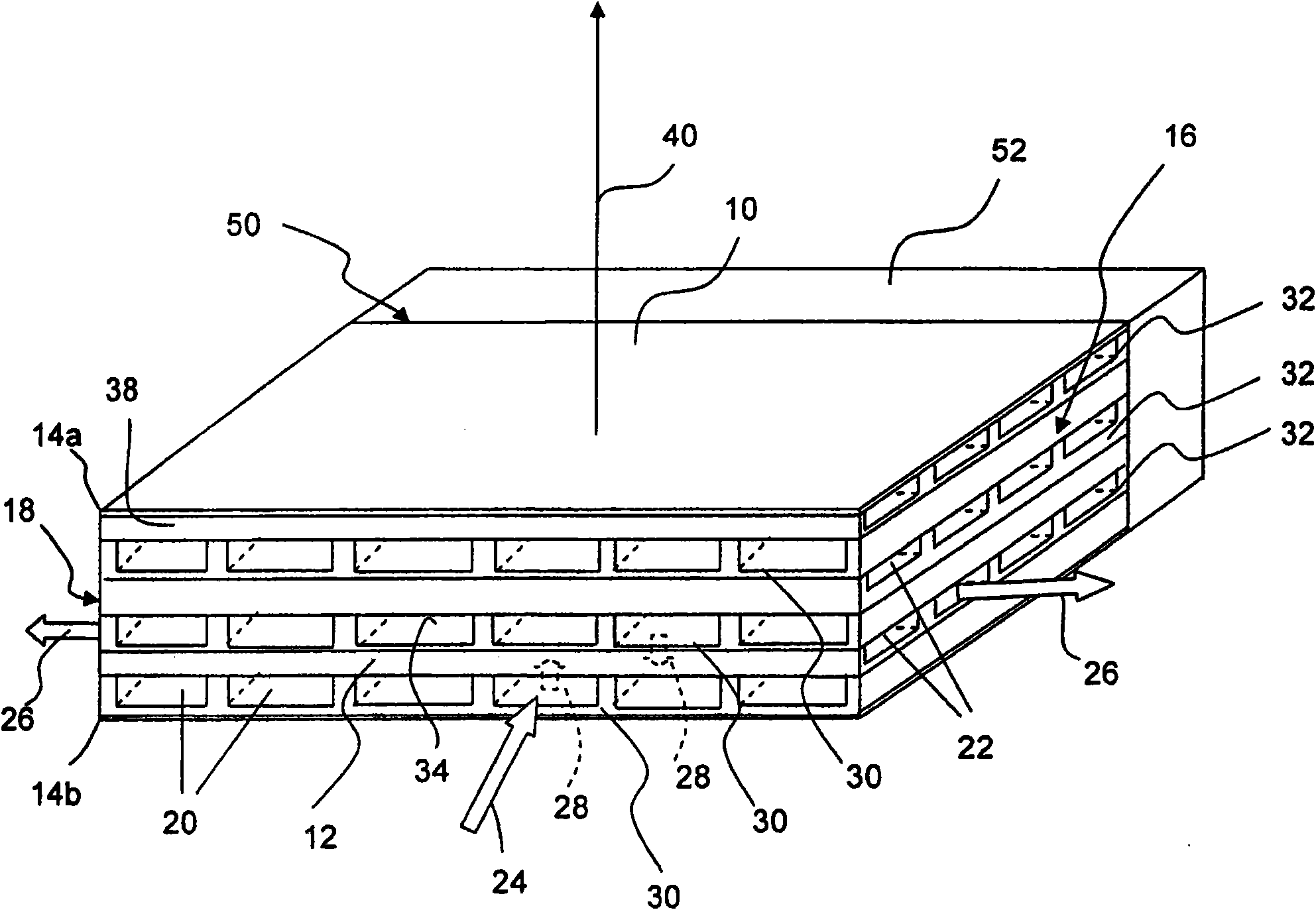
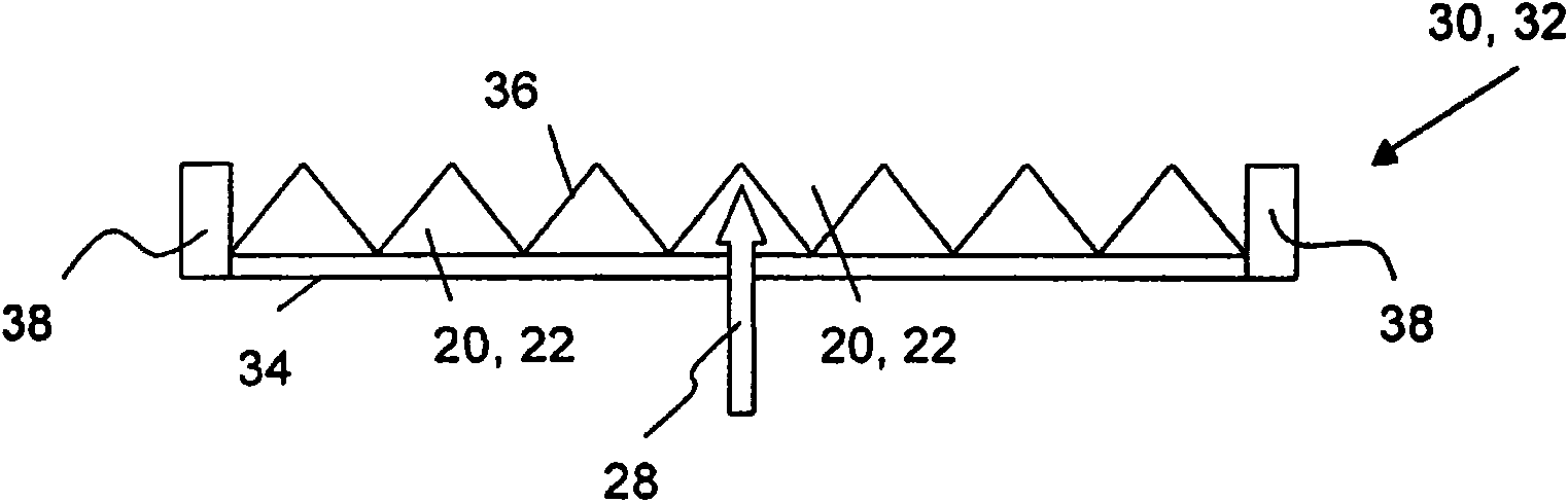
[0033] Figure 1a and Figure 1b A preferred filter 10 of a filter device (not shown) according to the invention is depicted in . The filter 10 has a feed inlet side 12 for the feed gas and filtrate outlets 16 , 18 for the filtrate. For example, in the case of raw exhaust gas as the feed fluid, the filter is exhaust gas free of carbon particles. The feed gas flows along the feed gas channels 20 arranged in the feed gas plate 30 , and the filtrate flows along the filtrate channels 22 arranged in the filtrate channel plate 32 . The plates 30 , 32 are stacked on top of each other in an alternating manner in the stacking direction 40 and are separated by a gas-permeable membrane 34 , wherein the channels 20 , 22 of successive channel plates 30 , 32 are arranged orthogonally, ie as Figure 1a As shown, the plates 30, 32 are rotated 90 degrees within each stacked layer.

[0034] The plates 30 , 32 have a comb-like shape with separator walls 36 (only a few are indicated with their ...


PUM


Abstract

The invention relates to a particulate filtration device (100) comprising a filter (10) with a feed inlet side (12) for a feed gas and an filtrate outlet (16, 18) for a filtrate, further comprising feed gas channels (20) and filtrate channels (22) and one or more diaphragms (34) between the feed inlet side (12) and the filtrate outlet (16, 18). Opposite to the feed inlet side (12) a particulate outlet (50) is arranged with a collector compartment (52) attached to the particulate outlet (50) for collecting particulates retained in the feed gas channels (20).

Description

technical field [0001] The invention relates to a particle filter device according to the preamble of claim 1 . Background technique [0002] Particulate filters are becoming an increasingly standard component in the exhaust aftertreatment of diesel engines. The most common particulate filters for heavy-duty engines are based on ceramic substrates such as cordierite or silicon carbide (SiC). The filters are typically fabricated as a single-piece matrix with a large number of parallel single-ended channels, some of which are closed at the entrance to the single piece and some of which are closed at the exit of the single piece. Particulates are filtered as exhaust gas is forced through the channel walls of the matrix. Efficiency is usually high, ie higher than 90%. Collected particulates are removed from the filter by oxidation. If there is NO in the exhaust 2 , then oxidation can occur at lower temperatures starting at about 250°C, or be removed by oxidation at higher t...

Claims


Application Information

Patent Timeline
Patent Type & Authority Applications(China)
IPC IPC(8): B01D46/12B01D46/52F01N3/022
CPCF01N3/035B01D2279/30F01N2330/14B01D46/526B01D46/005F01N3/2066F01N3/022F01N3/0253B01D46/12F01N3/0215
Inventor 伦纳特·安德森约纳斯·爱德华松爱德华·乔布森海耶·韦斯特伯格佩尔-奥洛夫·拉松奥弗·莫斯约根·克努特-尼尔森
Owner VOLVO TECH
Why Eureka
Try Eureka