Inductive load driving circuit
A technology of load driving circuit and switching circuit, which is applied in the direction of circuit devices, emergency protection circuit devices, electrical components, etc., and can solve the problem of large component size and other problems
- Summary
- Abstract
- Description
- Claims
- Application Information
AI Technical Summary
Problems solved by technology
Method used
Image

Examples
no. 1 example
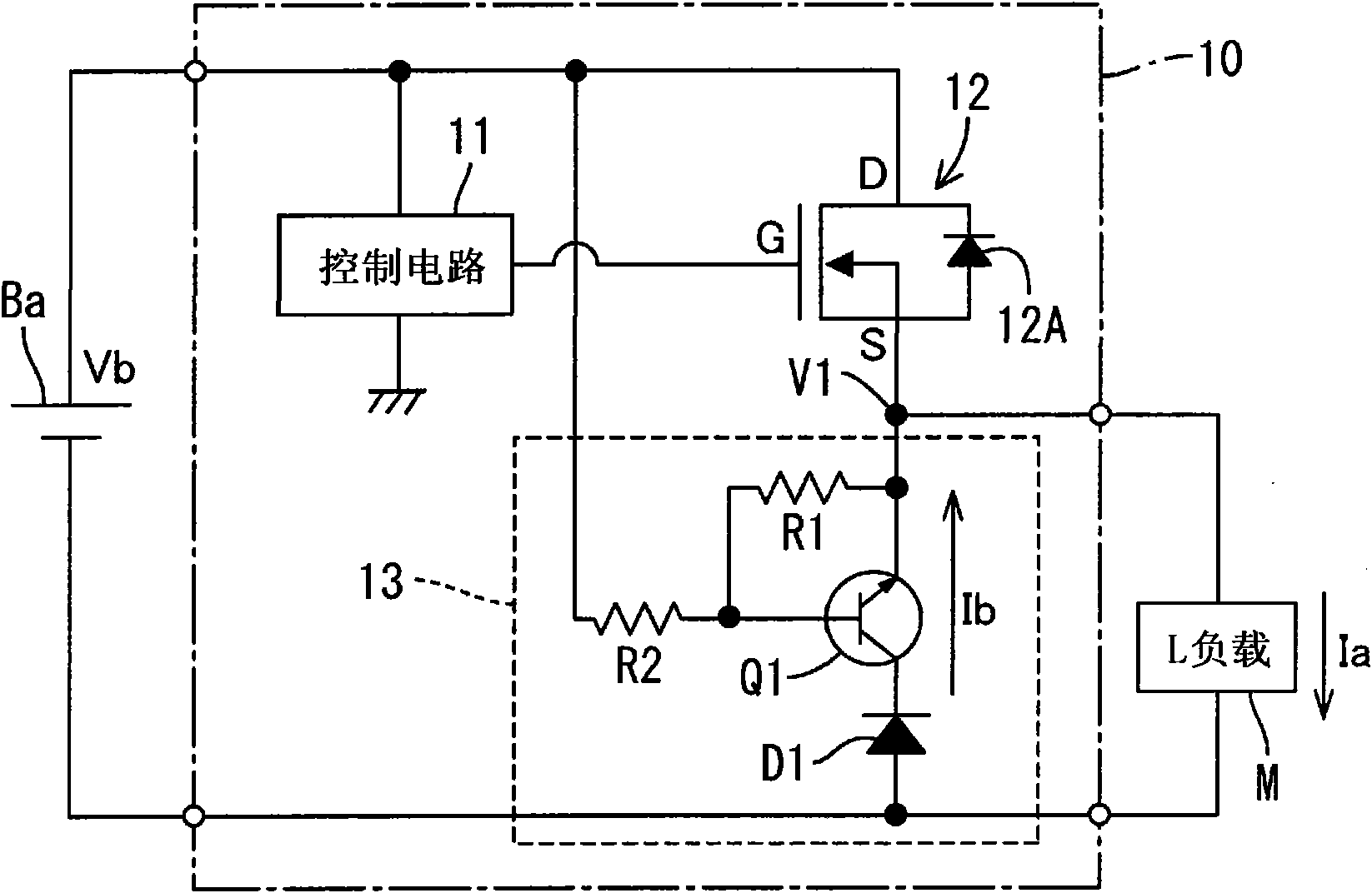
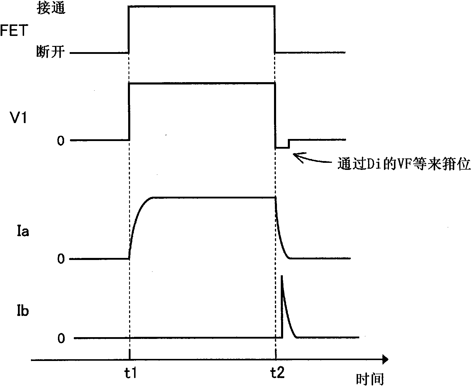
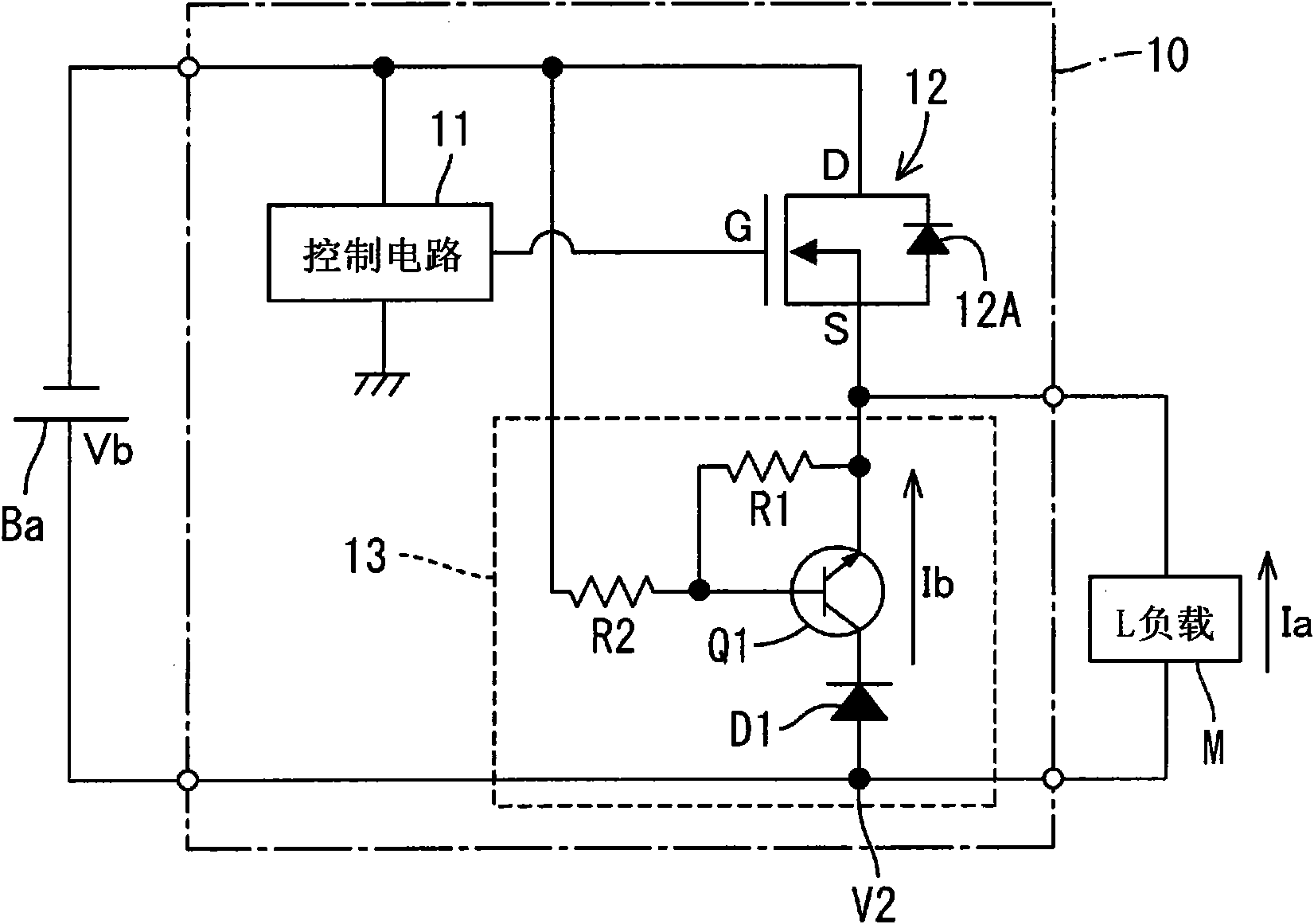
[0033] will refer to Figure 1 to Figure 4 A first embodiment according to the present invention will be described. figure 1 is a schematic block diagram of the inductive load drive circuit 10 according to the first embodiment of the present invention, which is in normal battery connection. figure 2 is the timing diagram in normal battery connection. image 3 is a schematic block diagram of the inductive load drive circuit 10 in reverse battery connection. Figure 4 is the timing diagram in reverse battery connection.
[0034] The inductive load driving circuit 10 includes a control circuit 11 , a switch circuit 12 , and a protection circuit 13 . In the present embodiment, the inductive load driving circuit 10 is equipped in an automobile and is connected between the battery Ba and the inductive load M (for example, an engine cooling fan driving motor) so as to operate drive control of the inductive load M.
[0035] For example, the control circuit 11 includes a CPU, and ...
no. 2 example
[0050] will refer to figure 2 , Figure 4 , Figure 5 ,as well as Figure 6 A second embodiment according to the present invention is described. Figure 5 is a schematic block diagram of the inductive load drive circuit 10 of the second embodiment, which is in normal battery connection. Figure 6 is a schematic block diagram of the inductive load drive circuit 10 of the second embodiment, in reverse battery connection. Note that the same configurations as those of the first embodiment will be designated by the same reference numerals, and descriptions will be omitted. Furthermore, since the configuration of the inductive load drive circuit 10 of the second embodiment differs from the first embodiment only in the configuration of the protection circuit, only the difference in the protection circuit will be described.
[0051] Such as Figure 5 As shown in , the protection circuit 13A of the inductive load driving circuit 10 of the second embodiment includes a field effec...
no. 3 example
[0061] Next, we will refer to figure 2 , Figure 4 , Figure 7 ,as well as Figure 8 A third embodiment according to the present invention will be described. Figure 7 is a schematic block diagram of the inductive load drive circuit 10 of the third embodiment, which is in normal battery connection. Figure 8 is a schematic block diagram of the inductive load drive circuit 10 of the second embodiment, in reverse battery connection. Note that the same configurations as those of the first embodiment will be designated by the same reference characters, and descriptions will be omitted. Furthermore, since the configuration of the inductive load drive circuit 10 of the third embodiment differs from the first embodiment only in the protection circuit, only the difference in the protection circuit will be described.
[0062] Such as Figure 7 As shown in , the protection circuit 13B of the third embodiment includes a relay RLY, a first diode (freewheel diode) D3, and a second d...
PUM
 Abstract
Description
Claims
Application Information
 - R&D
- Intellectual Property
- Life Sciences
- Materials
- Tech Scout
- Unparalleled Data Quality
- Higher Quality Content
- 60% Fewer Hallucinations
Browse by: Latest US Patents, China's latest patents, Technical Efficacy Thesaurus, Application Domain, Technology Topic, Popular Technical Reports.
© 2025 PatSnap. All rights reserved.Legal|Privacy policy|Modern Slavery Act Transparency Statement|Sitemap|About US| Contact US: help@patsnap.com