Armature magnetic core, armature, rotating electric machine, and compressor

A technology of armature and magnetic core, which is applied in the field of axial gap rotating motors, which can solve the problems of easy generation of eddy current and increase of magnetic circuit reluctance in armature teeth, and achieve simple stamping and increase of contact area , The effect of increasing the duty cycle

Inactive Publication Date: 2010-12-01
DAIKIN IND LTD
View PDF3 Cites 6 Cited by
  • Summary
  • Abstract
  • Description
  • Claims
  • Application Information

AI Technical Summary

Problems solved by technology

In this case, the reluctance of the magnetic circuit in the armature teeth increases, and eddy currents are easily generated in the armature teeth

Method used


Image

  • Armature magnetic core, armature, rotating electric machine, and compressor
  • Armature magnetic core, armature, rotating electric machine, and compressor
  • Armature magnetic core, armature, rotating electric machine, and compressor

Examples


no. 1 approach

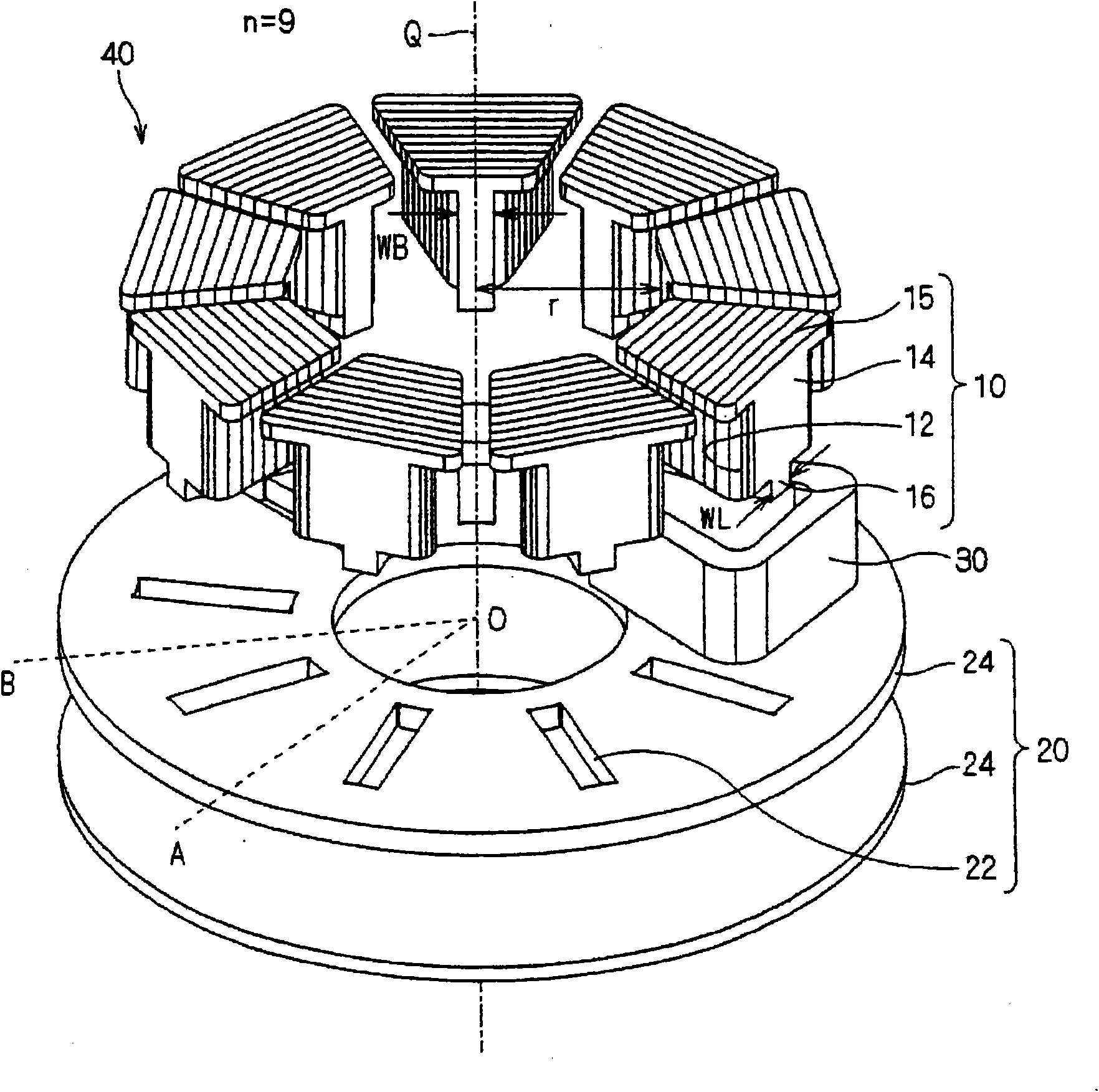
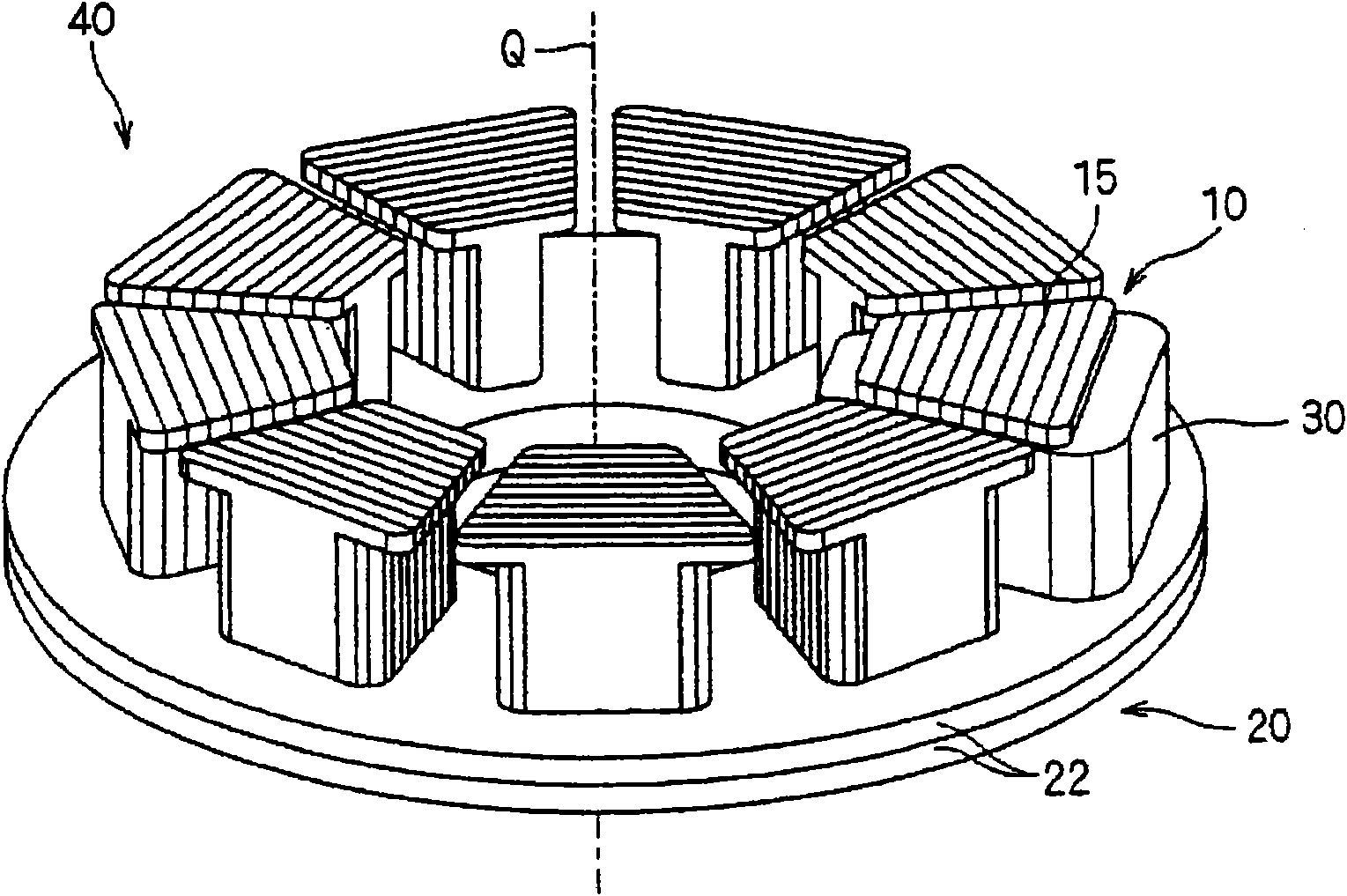
[0091] figure 1 It is an exploded perspective view of the armature 40 according to the first embodiment of the present invention, and is an exploded view along the rotation axis Q direction. also, figure 2 is an assembly drawing of the armature 40 . Such as figure 1As shown, the armature 40 includes the armature core 10, the yoke 20, and the armature winding 30, and is applied to, for example, an axial gap type motor (not shown). In addition, as long as there is no special description in the present invention, the armature winding does not refer to the individual wires that constitute it, but refers to the state in which the wires are wound together. This also applies to the attached drawings. In addition, the lead-out wires of the winding start end and the winding end end, and their connecting wires are also omitted in the drawings. figure 2 Only one armature winding is shown, and the other armature windings are omitted so that the form of the armature core can be illu...

no. 2 approach

[0115] In the above-mentioned first embodiment, the mode in which only the first cuboid portion 16 is buried in the concave portion 22 of the yoke 20 has been described, but the present invention is not limited thereto. Here, as a second embodiment of the present invention, an embodiment in which a flange portion 18 a is further provided at an end portion of the first cuboid portion 16 will be described with reference to the drawings. In addition, in the following description of the embodiment, unless otherwise specified, the same reference numerals are assigned to parts having the same functions as those of the above-mentioned first embodiment, and descriptions thereof will be omitted.

[0116] Figure 4 It is an exploded perspective view of an armature 40a according to the second embodiment of the present invention. Of the plurality of armature cores 10a attached to a yoke 20a, one armature core 10a is separated from the yoke 20a and is separated from the yoke 20a. The arma...

no. 3 approach

[0132] In the above-mentioned first and second embodiments, the mode in which the width of the first rectangular parallelepiped part 16 is equal to or smaller than the minimum width of the prism part 14 has been described. Although the embodiment in which the flange portion 18a is provided on the lower side of the frame 16 has been described, the present invention is not limited thereto. The width of the first cuboid portion 16 may be larger than the minimum width of the prism portion 14 . Here, as a third embodiment of the present invention, an embodiment in which the width of the first cuboid portion 16c is equal to or greater than the maximum value of the width of the prism portion 14 will be described with reference to the drawings.

[0133] Figure 8 It is an exploded perspective view of the armature 40c according to the third embodiment of the present invention, and is shown exploded in a direction along the rotation axis Q. FIG. also, Figure 9 is an assembly drawing...


PUM


Abstract

Disclosed is an armature magnetic core (10) which is formed by laminating a plurality of magnetic plates (12) punched in advance into a predetermined shape. The armature magnetic core (10) comprises prism portions (14) wound with armature coils (30), and first rectangular parallelepiped portions (16) to be buried in the recesses (22) of a yoke (20). The sectional shape of the prism portions (14) in a plane normal to a rotation axis (Q) is formed into a substantially trapezoidal shape, and the sectional shape of the first rectangular parallelepiped portions (16) in that plane is formed into a substantially rectangular shape. When the magnetic plates (12) are to be punched out, the punching step of the portions to constitute the prism portions (14) and the punching step of the portions to constitute the first rectangular parallelepiped portions (16) are separately performed. Near the boundaries of those two portions, the punchable areas of the molds to be used for the punching steps are overlapped by a predetermined width, thereby to avoid stress concentrations at the boundaries.

Description

technical field [0001] The present invention relates to a magnetic core for an armature and an armature, and is particularly applicable to an axial gap type rotating electrical machine. Background technique [0002] A rotating electrical machine includes an armature and field elements. In particular, in an axial gap type rotating electrical machine, the armature and the field element are arranged facing each other along the rotation axis with an air gap extending along a plane perpendicular to the rotation axis interposed therebetween. The armature has a yoke, armature teeth provided in the yoke, and a winding wound around the armature teeth. The field element is rotated by the rotating magnetic field generated by the armature. [0003] By passing alternating current to the windings, magnetic flux flows into the armature as this flux creates eddy currents in the yoke as well as in the armature teeth. [0004] Since the magnetic flux flows along the rotation axis in the ar...

Claims


Application Information

Patent Timeline
Patent Type & Authority Applications(China)
IPC IPC(8): H02K1/18F04C29/00H02K1/14
CPCF04C23/008F04C2240/40F04C2240/808F04C2240/803H02K1/148F04C23/02F04C29/0085H02K21/24
Inventor 浅野能成安本龙志木藤敦之
Owner DAIKIN IND LTD
Why Eureka
Try Eureka