Full-automatic feeding machine

An unwinding machine, fully automatic technology, applied in metal sawing equipment, tool manufacturing of sawing machine equipment, metal processing equipment, etc. Achieve the effect of low equipment cost, small footprint and low maintenance cost

Active Publication Date: 2010-12-08
BICHAMP CUTTING TECH HUNAN
View PDF7 Cites 2 Cited by
  • Summary
  • Abstract
  • Description
  • Claims
  • Application Information

AI Technical Summary

Problems solved by technology

[0003] In order to overcome the disadvantages of the existing feeding mechanism, such as the inconsistent length of single feeding, the low quality of saw band milling teeth, low feeding efficiency and unsafety, the present invention aims to provide a fully automatic feeding machine. Realize unattended automatic feeding, convenient feeding, consistent feeding length each time, and no bending of the saw band during feeding, which can significantly improve the quality of saw band milling teeth, safe and applicable

Method used


Image

  • Full-automatic feeding machine
  • Full-automatic feeding machine
  • Full-automatic feeding machine

Examples


Embodiment 1

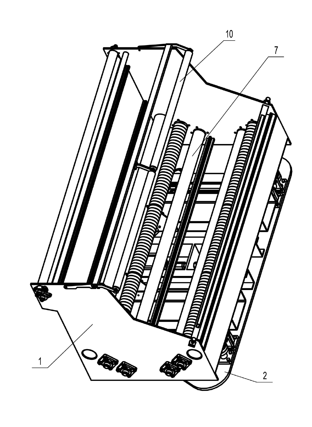
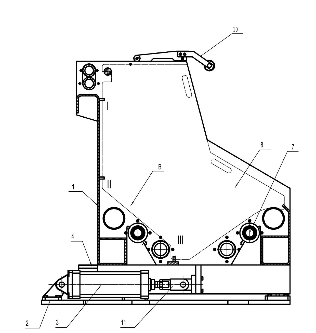
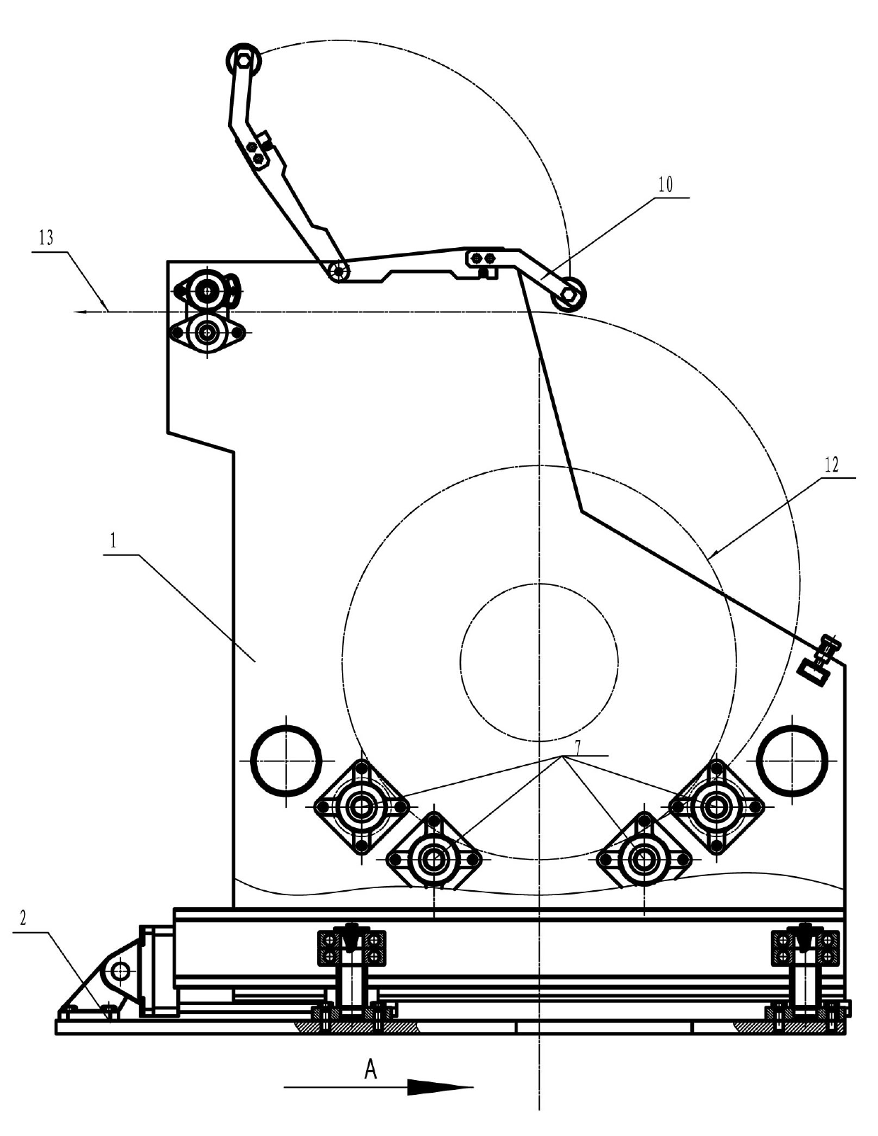
[0031] A fully automatic feeding machine, such as figure 1 and 2 As shown, it includes a frame 2, a cylinder 3 fixed on the frame 2, and a discharge support 1 connected to the cylinder through a joint 11; one side of the cylinder 3 is provided with an electromagnetic reversing valve for controlling the intake and exhaust of the cylinder 3. A supporting and limiting mechanism is also provided between the discharging bracket 1 and the frame 2 to make the discharging bracket 1 move linearly relative to the frame 2 in the direction A of cylinder advancement. Such as image 3 As shown, the structure of the support limit mechanism is that four support bearings 5 ​​mounted on the frame 2 for supporting the guide rail 4 are arranged below the guide rail 4 fixedly connected to the bottom end of the discharge bracket 1, and one side of the guide rail 4 There are four limit bearings 6 installed on the frame 2 to prevent the guide rail 4 from moving left and right.

[0032] The upper e...

Embodiment 2

[0038] A fully automatic feeding machine, comprising a frame 2, a reciprocating propulsion mechanism mounted on the frame 2, a discharging bracket 1 connected to one end of the reciprocating propulsion mechanism, and a gap between the discharging bracket 1 and the frame 2 A supporting and limiting mechanism is provided to make the discharging bracket 1 move linearly relative to the frame 2 in the advancing direction A of the reciprocating advancing mechanism. Such as Figure 6 As shown, the structure of the reciprocating propulsion mechanism is a crank linkage mechanism installed at the output end of the motor, and one end of the crank linkage mechanism is connected to the discharge bracket 1 through a joint 11 . Such as image 3 As shown, the structure of the support limit mechanism is that four support bearings 5 ​​mounted on the frame 2 for supporting the guide rail 4 are arranged below the guide rail 4 fixedly connected to the bottom end of the discharge bracket 1, and on...


PUM


Abstract

The invention discloses a full-automatic feeding machine for feeding band saw plates, comprising a stand, a reciprocating feed mechanism installed on the stand and a feeding support connected with one end of the reciprocating feed mechanism, wherein a supporting limit mechanism ensuring the feeding support to do linear motion relative to the stand in the feed direction A of the reciprocating feed mechanism is arranged between the feeding support and the stand. The machine realizes full-automatic feeding, dispenses with manual attendance and management, reduces the labor intensity of workers, improves the production efficiency, reduces the bend probability during composite feeding, improves the milling teeth quality, is safe and reliable, occupies less space and is low in equipment set cost and maintenance cost. Besides, the selection space of the specifications of the composites is larger during gear milling, and the number of the composite plates to be processed each time can be flexibly selected and is more than the number of the plates to be processed each time in the original feeding mechanisms.

Description

technical field [0001] The invention relates to a material discharging device, in particular to a fully automatic material discharging device for band saw disks. Background technique [0002] The existing feeding mechanism mainly relies on manual pulling, and its deficiencies are mainly reflected in the following aspects: I. The length of each pulling is inconsistent due to the inconsistent pulling force of artificial pulling; II. The artificial pulling causes the saw band to produce Very serious bending, which seriously affects the quality of saw band milling teeth; III, the efficiency of manual pulling is low, and each milling machine needs a special person to be responsible for pulling materials, the labor intensity of workers is high, and a little carelessness can easily lead to quality and safety accidents; IV, traditional When the feeding mechanism is loaded, due to the cascading method, the feeding height is getting higher and higher, making feeding more and more diff...

Claims


Application Information

Patent Timeline
IPC IPC(8): B23D65/04
Inventor 李栋梁
Owner BICHAMP CUTTING TECH HUNAN
Why Eureka
Try Eureka