
Clamping mechanism for milling of strip metal part for prefabricated building

A technology of clamping mechanism and metal parts, which is applied in the direction of metal processing machinery parts, metal processing equipment, milling machines, etc., can solve the problems of cumbersome clamping and fixing process, damage to welding dimensionality, and low processing efficiency, so as to improve milling quality, The effect of ensuring reliability and stability and improving processing efficiency

Pending Publication Date: 2018-10-12
ZHENJIANG ATLANTIC MODULAR SYSTEM LIMITED
View PDF6 Cites 0 Cited by
  • Summary
  • Abstract
  • Description
  • Claims
  • Application Information

AI Technical Summary

Problems solved by technology

[0003] Under normal circumstances, the prefabricated building wall is composed of channel steel, angle steel, rectangular tube, etc. before welding, channel steel, angle steel, and rectangular tube need to be butt-jointed to be firmly welded. There are errors in the fit between the thickness of the tube and the R angle and the corner. If the gap is too large, sometimes the welding wire will be wasted and the dimensionality of the welding will be damaged. Therefore, before the joint welding, it is necessary to mill the channel steel, angle steel, and rectangular tube However, traditional milling machines cannot clamp and fix long metal parts such as channel steel, angle steel, and rectangular tubes very well. The clamping and fixing process is very cumbersome, resulting in low processing efficiency and consuming a lot of labor.

Method used


Image

  • Clamping mechanism for milling of strip metal part for prefabricated building
  • Clamping mechanism for milling of strip metal part for prefabricated building
  • Clamping mechanism for milling of strip metal part for prefabricated building

Examples


Embodiment Construction

[0020] The present invention will be further illustrated below in conjunction with the accompanying drawings and specific embodiments, and it should be understood that these embodiments are only for illustrating the present invention and are not intended to limit the scope of the present invention.

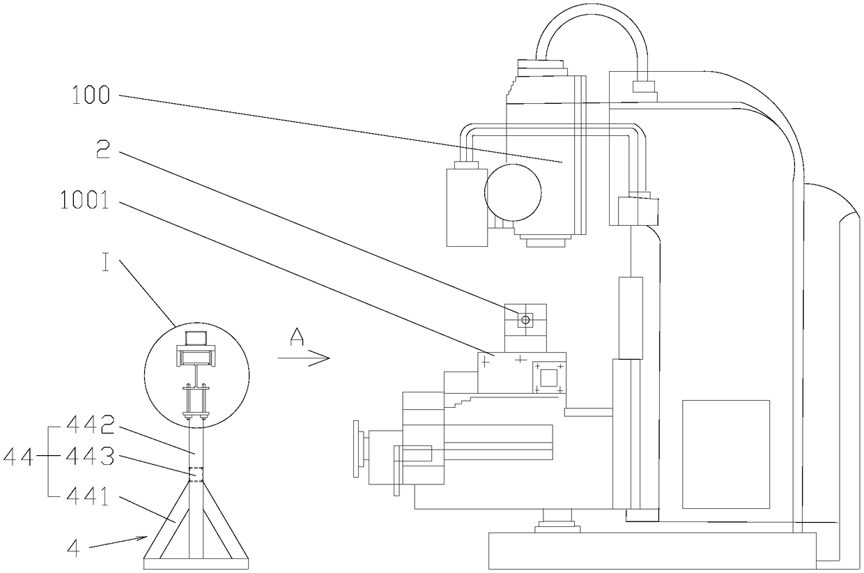
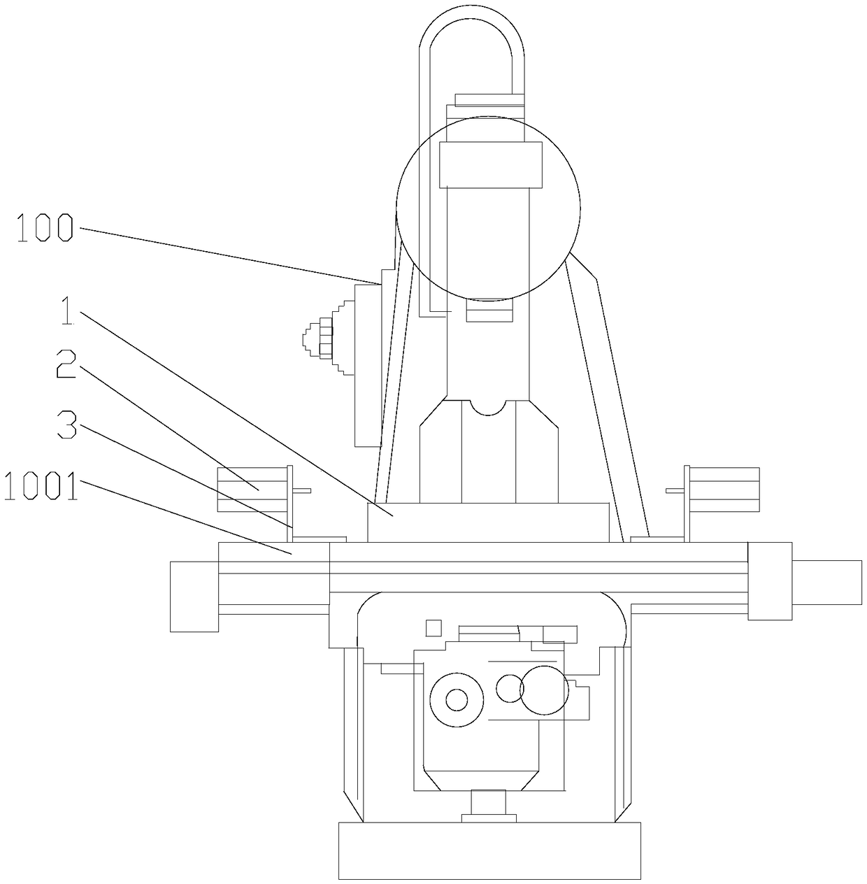
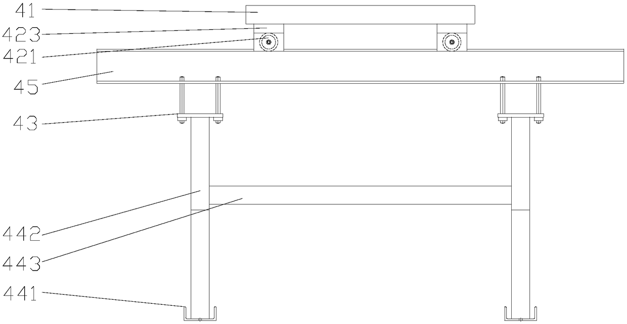
[0021] A clamping mechanism for milling of fabricated building strip metal parts, such as Figure 1~4 As shown, it includes an electromagnet platform 1, an electromagnetic button, a cylinder 2, a cylinder seat 3, and a translation support platform 4. Rod 45, translation assembly 42 includes roller 421, roller shaft 422, moving plate 423, the cross section of moving plate 423 is an inverted U shape, adjusting assembly 43 includes adjusting supporting plate 431, adjusting screw rod 432, adjusting nut 433, combined frame 44 comprises a tripod 441, a support bar 442, a reinforcing bar 443, and the support flat bar 45 is an I-shaped steel bar.

[0022] The electromagnet platform 1 is ...


PUM


Abstract

The invention discloses a clamping mechanism for milling of a strip metal part for prefabricated building. The clamping mechanism comprises an electromagnet platform, an electromagnetic button, air cylinders, air cylinder seats and a translation supporting table, wherein the electromagnet platform is mounted on a machining platform of a milling machine; the electromagnetic button is electrically connected with the electromagnet platform; the air cylinder seats are mounted on the machining platform and correspondingly arranged on the two opposite sides of the electromagnet platform along the transverse direction of the milling machine; the air cylinders are mounted on the air cylinder seats; the translation supporting table is arranged in front of the milling machine; a space A is left between the translation supporting table and the electromagnet platform; and the space A is less than the length B of the strip metal part. The clamping mechanism disclosed by the invention has the advantages that through the interaction among the electromagnet platform, the air cylinders and the translation supporting table, the process for clamping the strip metal part on the milling machine can besimplified, the operation time can be saved, and the clamping operation reliability and stability can be ensured; through the clamping mechanism, a row of strip metal parts can be milled on the milling machine at a time; and accordingly, the machining efficiency can be improved, the labor intensity can be reduced, and the milling quality of the milling machine can be improved.

Description

technical field [0001] The invention relates to a clamping mechanism, in particular to a clamping mechanism for milling long metal pieces. Background technique [0002] Prefabricated modular building is an assembly technology. It uses prefabricated modular components, such as walls, to assemble various houses, which are easy to construct and flexible to assemble. The modular components are prefabricated in the factory, which facilitates the organization of industrialized production, improves work efficiency, reduces material consumption, and is less affected by seasons. Modular buildings have the characteristics of fast construction speed, good seismic performance, large usable area, light building weight, simple construction, flexible assembly, low labor and material consumption, and modular components can be designed, so they have good application value in urban construction. [0003] In general, the prefabricated building wall is composed of channel steel, angle steel, r...

Claims


Application Information

Patent Timeline
Patent Type & Authority Applications(China)
IPC IPC(8): B23C1/025B23Q1/25
CPCB23C1/025B23Q1/25
Inventor 江培刚
Owner ZHENJIANG ATLANTIC MODULAR SYSTEM LIMITED
Learn More