Plate type ice storage trough

An ice storage tank, plate technology, applied in the heating method, fixed plate conduit assembly, application and other directions, can solve the problems of occupying building space and air-conditioning water channel blockage, etc., to achieve easy heat exchange enhancement, uniform ice thickness, avoid deformation effect

Inactive Publication Date: 2010-12-08
SHANGHAI AIRUTE AIR CONDITIONING SYST
View PDF1 Cites 3 Cited by
  • Summary
  • Abstract
  • Description
  • Claims
  • Application Information

AI Technical Summary

Problems solved by technology

The ice storage tank has some defects, such as the air-conditioning water channel may be blocked when the ice is melted; because t

Method used


Image

  • Plate type ice storage trough
  • Plate type ice storage trough
  • Plate type ice storage trough

Examples


Embodiment approach 1

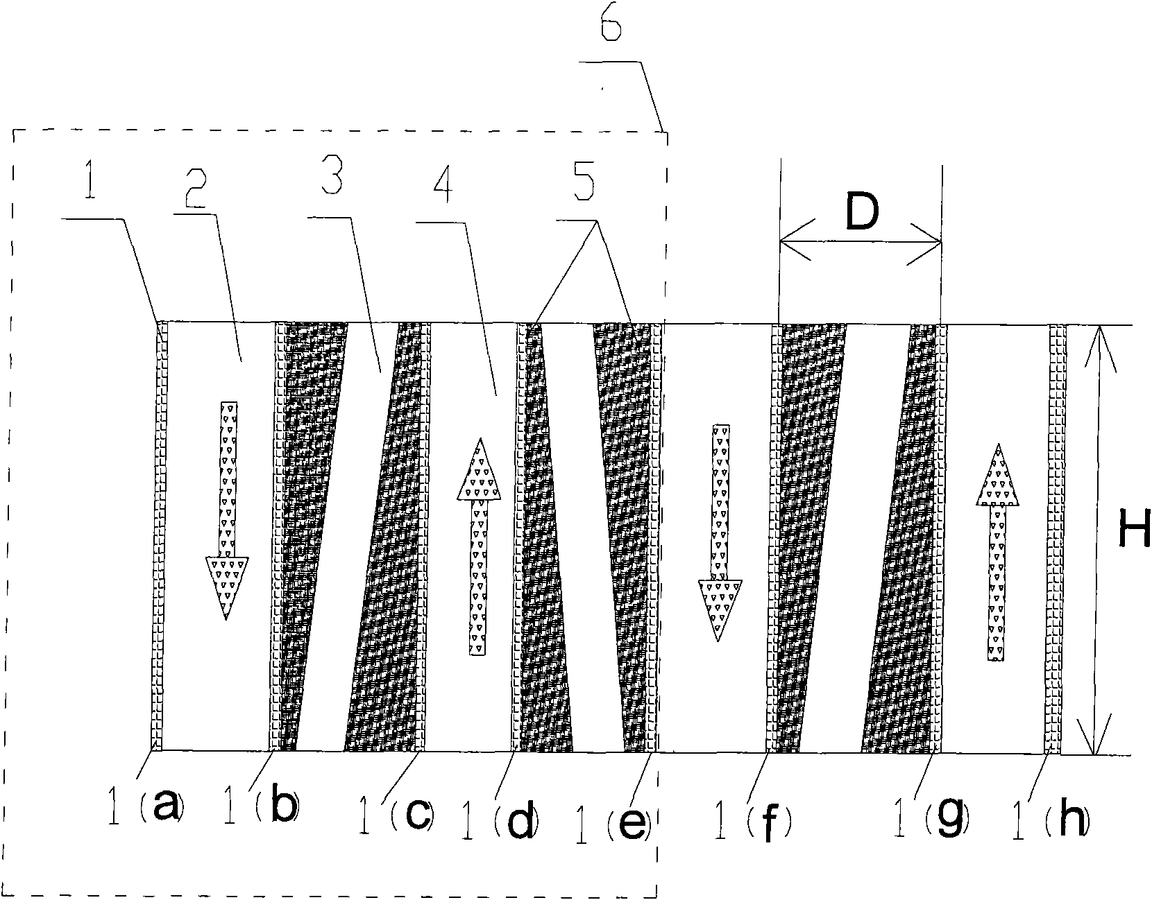
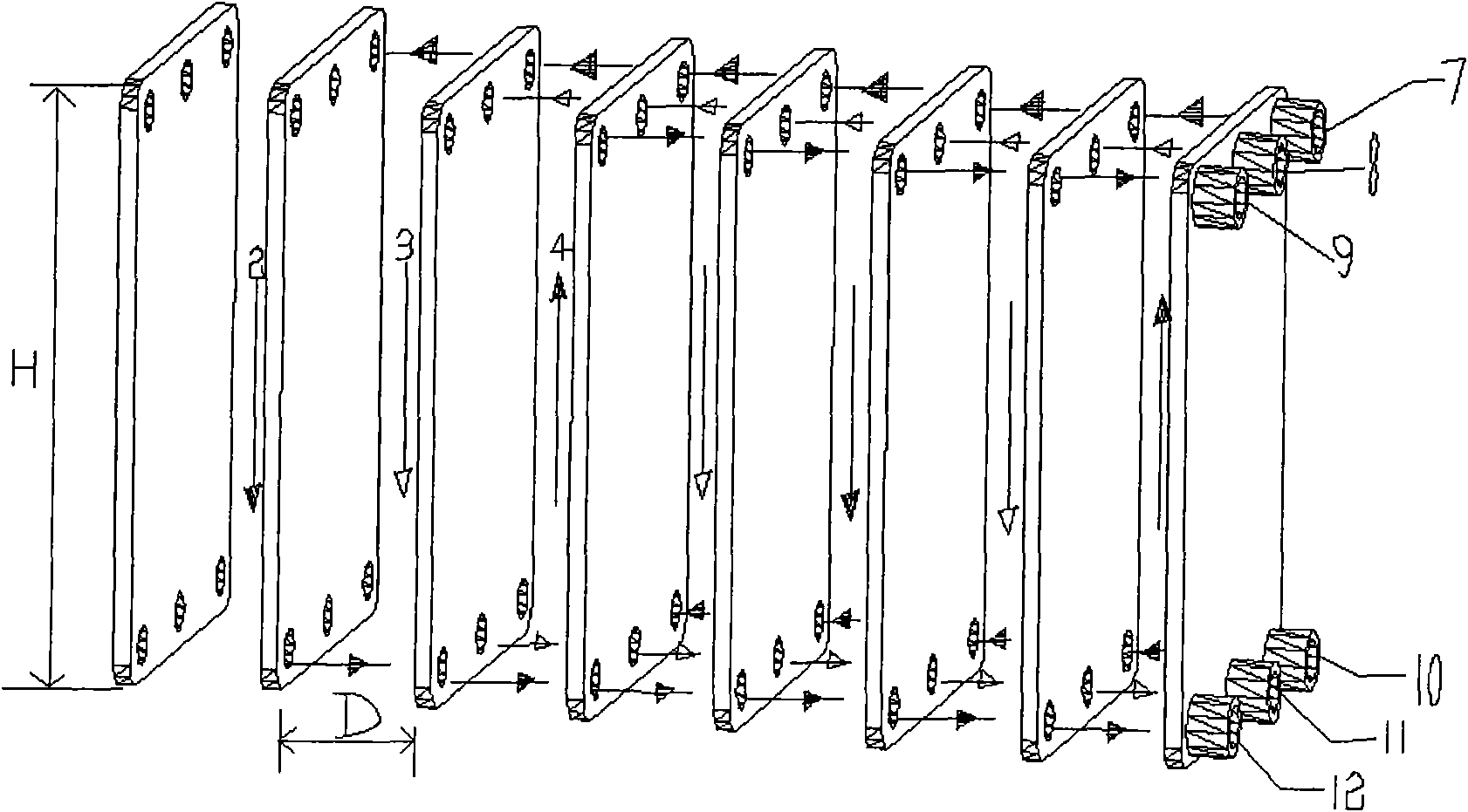
[0021] figure 1 is a sectional view of the first embodiment of the present invention when storing ice, figure 2 is a schematic flow diagram of the first embodiment of the present invention. In this embodiment, the direction of the plate-type ice storage tank heat exchange plate is perpendicular to the ground. The plate ice storage tank includes a set of heat exchange plates 1(a), 1(b), 1(c), 1(d), 1(f), 1(g) and 1(h). An air-conditioning water ice storage channel 3 is formed between the heat exchange plates 1(b) and 1(c), 1(d) and 1(e), and 1(f) and 1(g). A low-temperature fluid channel 2 is formed between the heat exchange plates 1(a) and 1(b), 1(e) and 1(f), and the flow direction of the low-temperature fluid in the low-temperature fluid channel 2 is upward. A low-temperature fluid channel 4 is formed between the heat exchange plates 1(c) and 1(d), 1(g) and 1(h), and the flow direction of the low-temperature fluid in the low-temperature fluid channel 4 is downward. The ...

Embodiment approach 2

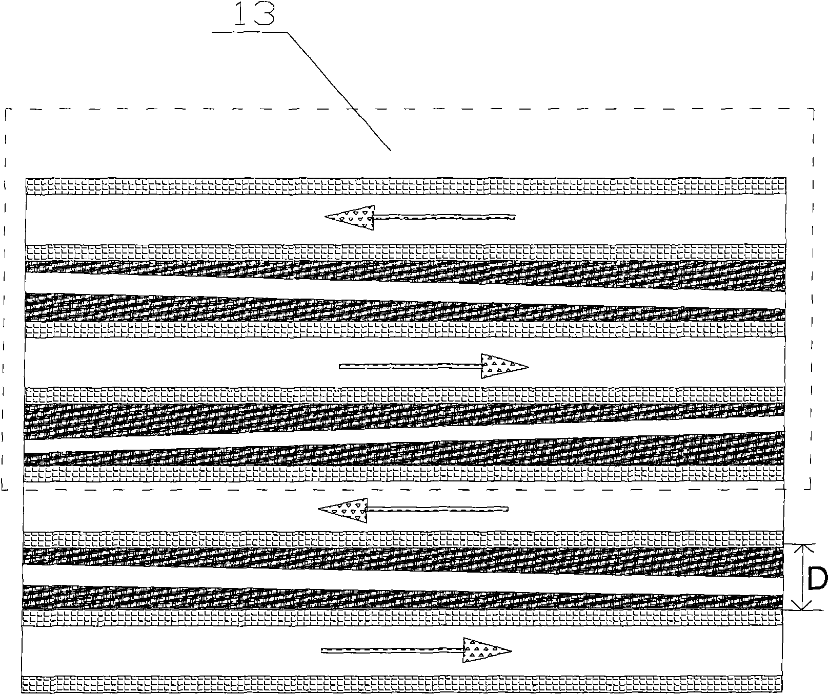
[0025] image 3 It is a sectional view of another embodiment of the present invention during ice storage. In this embodiment, the direction of the heat exchange plate is parallel to the ground. In this embodiment, the flow directions of the cryogenic fluid and the air-conditioning water are both along the horizontal direction. The ice storage method is the same as when the heat exchange plate is placed vertically, so it will not be repeated here. The distance between the heat exchange plates of the air-conditioning water ice storage channel, the distance D shown is 40mm-120mm. The plate ice storage tank can be composed of many heat exchange plates, and the most basic structural unit is the basic structure 13 shown in the figure.

[0026] The material of the heat exchange plate of the plate type ice storage tank is any one of stainless steel plate or heat conducting plastic plate.

[0027] The heat exchange plate of the above-mentioned plate ice storage tank is any one of co...


PUM


Abstract

The invention relates to a plate type ice storage trough mainly comprising a group of heat exchange plates with through holes. The plate type ice storage trough is structurally characterized in that air-conditioning water channels are formed between the heat exchange plates; low-temperature fluid channels are formed between the heat exchange plates; the air-conditioning water channels and the low-temperature fluid channels are mutually alternated; the spacings of the air-conditioning water channels between the heat exchange plates are 40-120 mm; and the heights of the heat exchange plates are 0.2-3.0 m. The invention can reduce the system cost by 20-30 percent by combining a heat exchanger and the ice storage trough of an ice storage air-conditioning system into a whole, overcomes the defects of low ice melting speed of ice melting modes, i.e. internal ice melting, ice balls, ice plates, and the like, by adopting a close type external ice melting mode and provides the technical support for low-temperature air supply; and more importantly, the invention is beneficial to the modularization of the ice storage trough and the miniaturization and the domestication of the ice storage air-conditioning system due to a unique form.

Description

technical field [0001] The invention relates to the technical field of ice storage air conditioning, in particular to an ice storage tank in an ice storage air conditioning system. Background technique [0002] Due to the rapid growth of my country's economy, electricity consumption has also increased rapidly, especially during the peak hours of electricity consumption, and the power supply is insufficient in peaks and excessive in troughs. Therefore, the power supply department adopts a time-of-use electricity price policy to shift peaks and fill valleys. The power consumption of air conditioners is an important part of the total power consumption of the power grid, and it is one of the reasons for the peak-valley load difference of the power grid. The ice-storage air-conditioning system uses the low-priced low-peak electricity to store ice and store cold energy at night, and uses less or no main engine cooling during the peak period when electricity prices are more expens...

Claims


Application Information

Patent Timeline
IPC IPC(8): F28D9/00F24F5/00
Inventor 张小力
Owner SHANGHAI AIRUTE AIR CONDITIONING SYST
Why Eureka
Try Eureka