Filters for removal of volatile siloxanes and lifetime extension of photcatalytic devices

A filter, volatile technology, applied in the direction of respiratory protection devices, chemical instruments and methods, applications, etc., can solve the problem of catalytic ability loss over time

Inactive Publication Date: 2010-12-08
CARRIER CORP
View PDF1 Cites 6 Cited by
  • Summary
  • Abstract
  • Description
  • Claims
  • Application Information

AI Technical Summary

Problems solved by technology

Currently available systems exhibit signif

Method used


Image

  • Filters for removal of volatile siloxanes and lifetime extension of photcatalytic devices
  • Filters for removal of volatile siloxanes and lifetime extension of photcatalytic devices

Examples


Embodiment Construction

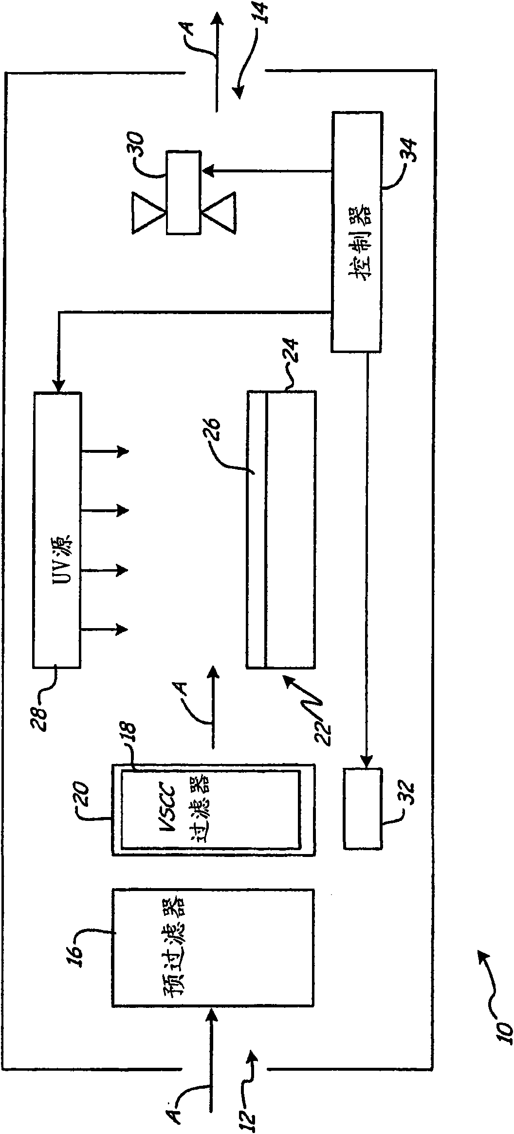
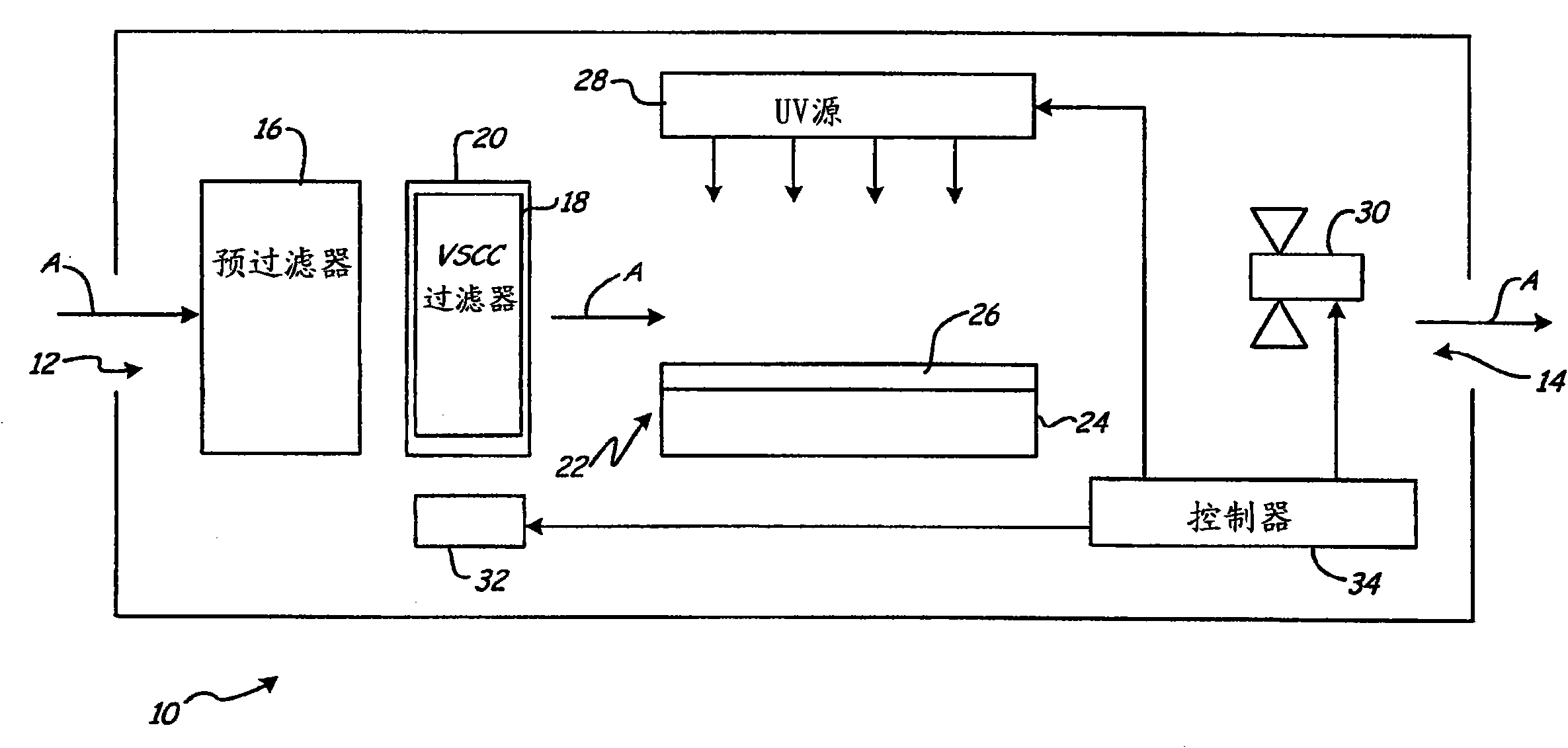
[0009] Figure 1 is a schematic diagram of an ultraviolet photocatalytic oxidation air purification system 10, which includes an inlet 12, an outlet 14, an optional pre-filter 16, a VSCC filter 18, a filter surface treatment 20, a photocatalytic reactor 22 (which It includes a substrate 24, a photocatalytic coating 26 and a UV source 28), a fan 30, a mineralization device 32 and a controller 34.

[0010] The ambient air is drawn into the system 10 through the inlet 12 through the fan 30. The air flow A passes through the pre-filter 16 and the VSCC filter 18 and then passes through the photocatalyst reactor 22 and the fan 30 to the outlet 14. The pre-filter 16 removes dust and particles by trapping the dust and particles. The VSCC filter 18 removes volatile silicon-containing compounds (VSCC) so that they do not reach the photocatalytic coating 26 and reduce the performance of the photocatalytic reactor 22. Other volatile organic compounds can also be removed by adsorption on any...


PUM


Abstract

A filter (20) for use in an ultraviolet photocatalytic oxidation air purification system (10) having a filter surface treatment (20) that enhances removal of volatile silicon-containing compounds (VSCCs). The surface treatment (20) may create an acidic site on the filter (20), increase the surface area of the filter (20), or facilitate preferential interaction between the surface and the VSCCs, thereby promoting the VSCCs to bond with the VSCC filter (20). Removal of the VSCCs prior to the VSCCs reaching the photocatalyst (26) increases the useful life of the photocatalyst (26).

Description

Background of the invention [0001] The present invention generally relates to the use of ultraviolet photocatalytic oxidation (UV-PCO) processes to improve fluid decontamination in fluid purifier systems, especially air purification systems. More specifically, the present invention relates to the removal of volatile silicon-containing compounds (VSCC) by improving the surface characteristics of the VSCC filter, which is located upstream of the photocatalyst in the UV-PCO air purifier system. [0002] Some buildings use air purification systems to remove airborne substances such as benzene, formaldehyde and other pollutants from the air supply. Some of these purification systems include photocatalytic reactors, which utilize a substrate or cartridge containing a photocatalyst, which is usually an oxide-based semiconductor. When placed under a suitable light source, typically under a UV light source, the photocatalyst oxide interacts with water molecules carried by the air to form ...

Claims


Application Information

Patent Timeline
IPC IPC(8): A62B7/08F24F8/167F24F8/95
CPCB01D2253/102F24F3/16B01D2255/1025B01D2253/206B01D2257/556B01D2255/1026B01D2255/1023B01D2255/802B01D2257/706B01D2253/108B01D2251/70B01D2255/104B01D2255/9207B01D2257/708B01D2253/306B01D2255/702B01D2255/1021B01D53/869B01D2253/11B01D2253/202B01D53/8668F24F2003/1667B01D2255/30B01D2255/20707B01D2255/1028B01D2251/506B01D2255/50B01D53/72B01D53/04B01D2255/20738B01D2255/106B01D2259/804F24F8/22F24F8/95F24F8/167
Inventor W·R·施米德特N·E·奇波利尼S·阿尔塞诺
Owner CARRIER CORP
Why Eureka
Try Eureka