Numerical control machine tool for machining bearing retainer

A technology for bearing cages and CNC machine tools, which is applied to metal processing machinery parts, metal processing equipment, manufacturing tools, etc., and can solve problems that affect the accuracy of processed workpieces and low work efficiency

Active Publication Date: 2010-12-15
SHENYANG MASCH TOOL CO LTD
View PDF6 Cites 3 Cited by
  • Summary
  • Abstract
  • Description
  • Claims
  • Application Information

AI Technical Summary

Problems solved by technology

In this way, the work efficiency is low, which affects the accuracy requirements of the workpiece.

Method used


Image

  • Numerical control machine tool for machining bearing retainer
  • Numerical control machine tool for machining bearing retainer
  • Numerical control machine tool for machining bearing retainer

Examples


Embodiment Construction

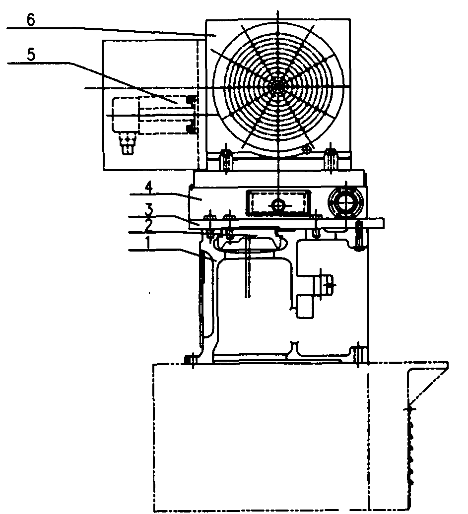
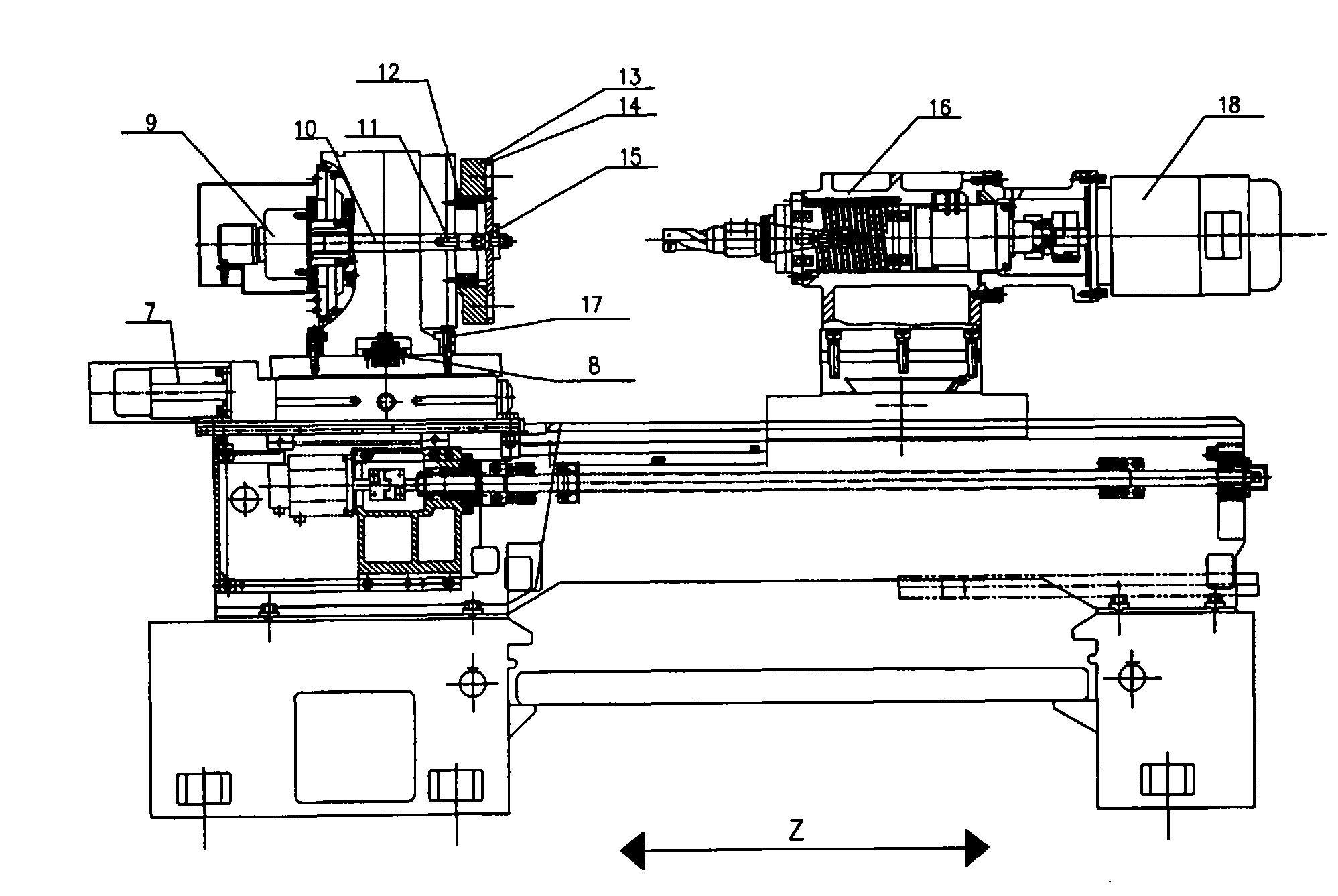
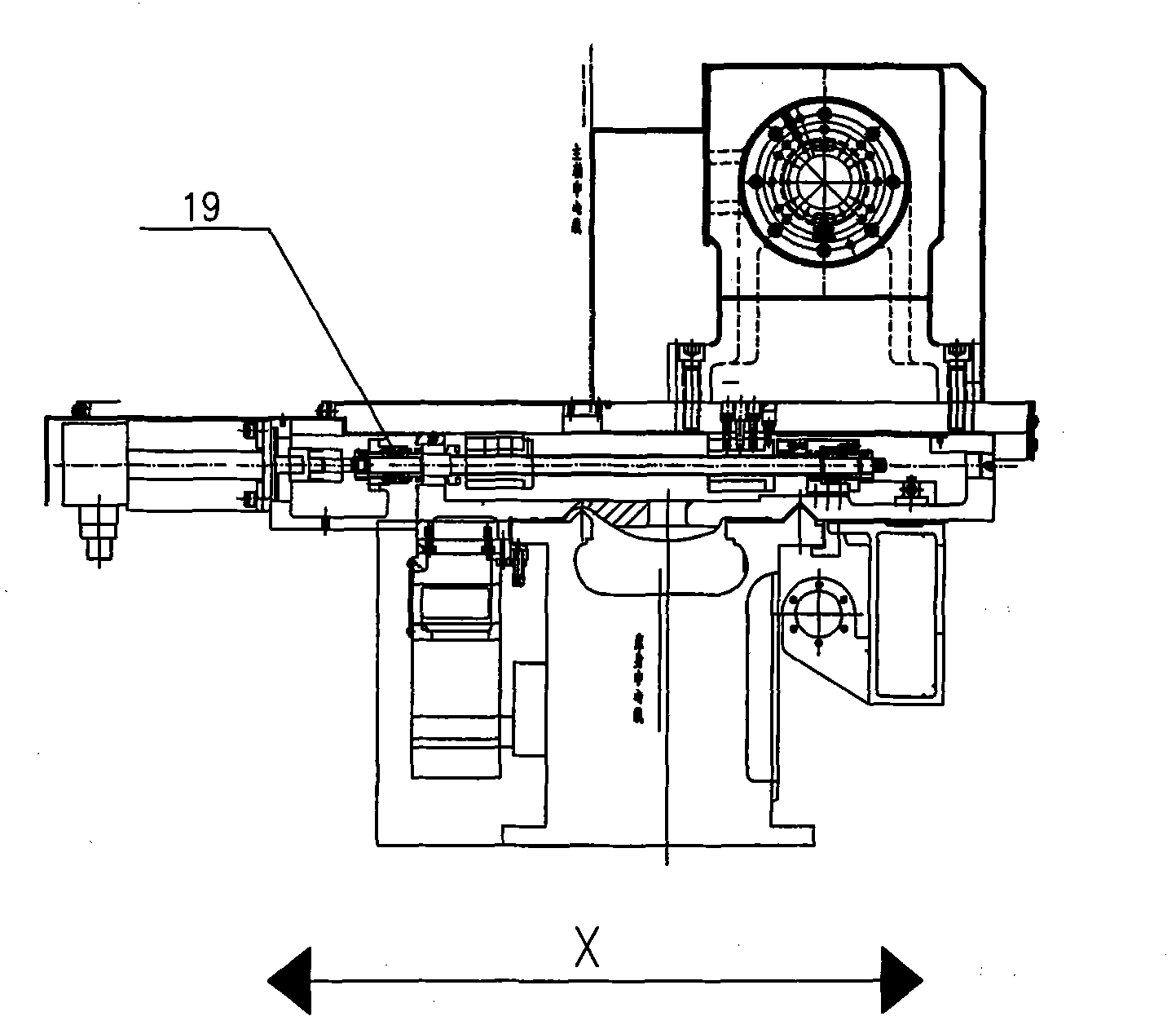
[0018] CNC machine tools for machining bearing cages, including bed, control system, hydraulic oil circuit and cooling system, each axis is equipped with a motor, and the B-axis horizontal rotary table on the left side of the bed is fixed to the bed, and its characteristic is that the B-axis The upper center of the horizontal rotary table has a positioning hole, and the bottom of the C-axis vertical rotary table has a shaft hole corresponding to the positioning axis. The positioning axis is placed on the positioning axis of the B-axis horizontal rotary table and the C-axis vertical rotary table. inside the hole, see Figure 4 , and fix the positioning axis and the C-axis table on the B-axis table with bolts and positioning pins respectively; There is a slide plate on the saddle to move along the X-axis screw in the saddle, the Z-direction on the slide plate fixes the tool headstock, and the tool headstock is set on the slide plate and the bed saddle to move in the X and Z dire...


PUM


Abstract

A numerical control machine tool for machining a bearing retainer comprises a body, a control system, a hydraulic circuit and a cooling system. Each axis is equipped with a motor and a B-axis horizontal rotating table on the left of the body is fixed with the body. The machine tool is characterized in that a locating hole is arranged in the circle center on the upper part of the B-axis horizontal rotating table; an axis hole corresponding to a locating axis is arranged at the bottom of a C-axis vertical rotating table; the locating axis is arranged in locating axis holes of the B-axis horizontal rotating table and the C-axis vertical rotating table and is fixed on a B-axis work table together with a C-axis work table by a bolt and a locating pin respectively; a fixture is installed on a C-axis vertical turntable of the numerical control machine tool; a saddle is arranged on the right of the Z-direction body; a sliding plate is arranged on the saddle and moves along an X axial screw in the saddle; and a cutter spindle housing is fixed on the sliding plate in the Z direction and can move on the sliding plate and the saddle in the X and Z directions. The numerical control machine tool can realize one-time assembling and fixing, thus satisfying precise machining of the part end face holes and the circumference holes of the bearing retainer.

Description

technical field [0001] The invention relates to machine tool manufacturing in mechanical processing, and is a special numerical control machine tool specially developed for processing bearing cages. Background technique [0002] At present, when processing the end face and circumferential hole of the bearing cage in China, most of the machine tools use semi-automatic programmable controllers, use the dividing head to index the servo motor, set the hand wheel on the base of the dividing head, and manually rotate the angle to perform indexing by dialing the meter After that, lock it manually. The bed is a sliding guide rail and is fed by hand. In this way, the work efficiency is low, which affects the accuracy requirements of the processed workpiece. Contents of the invention [0003] The purpose of the present invention is to provide a numerically controlled machine tool for machining bearing cages, so as to realize precise machining of the end face holes and circumferent...

Claims


Application Information

Patent Timeline
Patent Type & Authority Applications(China)
IPC IPC(8): B23B41/02B23B47/00B23Q1/25B23Q5/40
Inventor 常宝强李晓雷杜军刘大敏陈丽文戴德明杜海龙李平徐大伟魏广元刘萍陶秀玉刘锰
Owner SHENYANG MASCH TOOL CO LTD
Why Eureka
Try Eureka