Wheel rim driving wheel brake device

A brake device and wheel technology, which is applied to hydraulic brake transmission devices, brakes, brake components, etc., can solve the problems of low braking strength, increased brake pressure response time, and high motor cost, so as to improve the pressure response speed , shorten the braking distance, improve the effect of safety

Inactive Publication Date: 2010-12-15
TSINGHUA UNIV
View PDF4 Cites 13 Cited by
  • Summary
  • Abstract
  • Description
  • Claims
  • Application Information

AI Technical Summary

Problems solved by technology

The advantages of ordinary vacuum booster devices are low cost, mature technology and good reliability; the disadvantages are: in frequent braking conditions, it will consume a lot of physical strength of the driver and increase the driver's work intensity; in the anti-lock braking system (ABS ) or the Electronic Stability Control Program (ESP) is working, as the brake pressure fluctuates, the foot on the brake pedal is subject to corresponding impact, and the driving comfort is not good
The advantage of this device is that it is improved and developed on the basis of the existing automobile hydraulic control unit, and the manufacturing process is mature; the disadvantage is that it relies on the high-pressure accumulator to generate the brake hydraulic pressure, and once the high-pressure accumulator fails, it will seriously affect the braking. System Braking Efficiency
The advantages of this device are: it overcomes the impact problem of the brake pressure on the brake pedal, the motor control technology is mature, the control is convenient, and the system reliability is high; the disadvantage is: the high price of the motor leads to high cost
The actuators of the above two electronic hydraulic brake devices are located above the suspension of the vehicle and cannot be integrated with the brake wheel cylinder, so the structure is not compact; in addition, brake hoses are used in the brake pipelines, which increases the Brake pressure response time; and the electric energy used by the motor comes from the engine to drive the generator, which leads to low energy utilization efficiency in the energy conversion process
The electro-mechanical braking system, like the electro-hydraulic braking system, adopts the wire control technology. The difference is that the electro-mechanical braking system directly uses the motor to actuate the brake friction plate to generate friction to brake the wheels. The advantage is; the system responds quickly; the disadvantage is: the cost of the motor is high, and the electric energy consumed by the motor comes from the engine, which also leads to low energy utilization efficiency and low braking intensity, so it is usually used for auxiliary functions such as hill starting and temporary parking.

Method used


Image

  • Wheel rim driving wheel brake device
  • Wheel rim driving wheel brake device
  • Wheel rim driving wheel brake device

Examples


Embodiment Construction

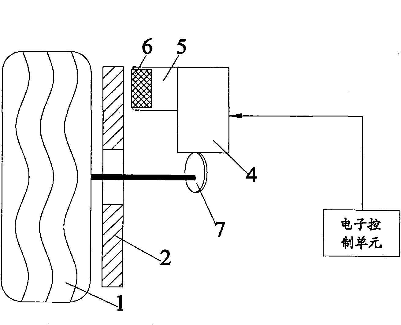
[0024] The wheel edge-driven wheel braking device proposed by the present invention can have many different structural forms,

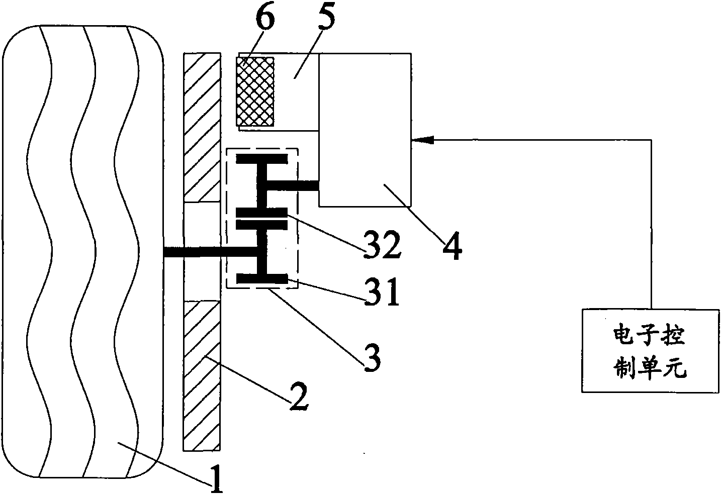
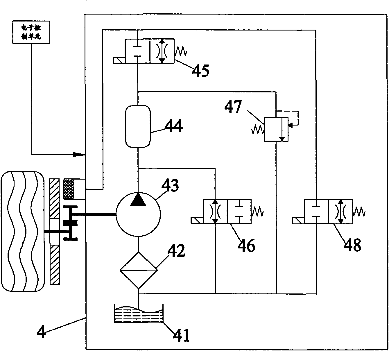
[0025] The braking device of the first structural form, such as figure 1 As shown, it includes: a transmission mechanism 3 for transmitting the kinetic energy of the rotation of the wheel 1 to the wheel hydraulic control unit 4 . Transmission mechanism 3 comprises driving gear 31 and driven gear 32, and driving gear 31 is coaxially installed with automobile wheel 1, and driven gear 32 links to each other with wheel side hydraulic control unit 4; And wheel side hydraulic control unit 4, its structure is as follows figure 2 As shown, it is used to transmit the kinetic energy from the wheel rotation to the brake wheel cylinder 5 of the vehicle according to the instruction of the vehicle electronic control unit. The wheelside hydraulic control unit includes an oil pump, a high-pressure accumulator 44, a discharge valve 46, a boost valve 45, a pressure l...


PUM


Abstract

The invention relates to a wheel rim driving wheel brake device, and belongs to the technical field of automobile manufacture. The device comprises a transmission mechanism and a wheel rim hydraulic control unit, wherein the transmission mechanism is used for transferring kinetic energy of wheel rotation to the wheel rim hydraulic control unit; and the wheel rim hydraulic control unit is used for transferring the kinetic energy from wheel rotation to an automobile brake cylinder according to the instruction of an automobile electronic control unit. The wheel rim driving wheel brake device directly acquires the kinetic energy of wheel rotation, provides liquid kinetic energy for the work of a brake system, realizes active safe control by adopting the existing control strategy of an automobile such as anti-lock brake or electronic stable control and the like during braking, and provides convenient and simple solution for kinetic control of vehicles; the device shortens the brake distance of the automobile and improves the driving safety; the device does not bring impact to a driver due to pressure change of a hydraulic system during working, so the driver feels more comfortable; and the device can be used for assisting the driver in hill start and auxiliary stop.

Description

technical field [0001] The invention relates to a wheel edge-driven wheel braking device, which belongs to the technical field of automobile manufacturing. Background technique [0002] In the development and evolution of the wheel braking system, the development of reliable and energy-efficient braking devices has been throughout the entire process. At present, due to the rapid development of electronic technology, the brake device has begun to try to use the wire control technology (DBW, Drive ByWire), that is, the brake pedal is connected to the sensor to provide a braking strength signal, and the specific braking action is performed by the brake device. verb: move. The types of brake systems for the current wheels include: common vacuum booster brake devices, electro-hydraulic brake devices (EHB, Electric Hydraulic Brake), electro-mechanical brake devices (EMB, Electro Mechanical Brake) and the like. Among them, the ordinary vacuum booster uses the force of the driver ...

Claims


Application Information

Patent Timeline
IPC IPC(8): B60T1/10B60T11/10
Inventor 贺林李亮王治中宋健李红志王伟玮
Owner TSINGHUA UNIV
Why Eureka
Try Eureka