Ship propeller

A technology for propellers and ships, applied in ship propulsion, propulsion components, propulsion engines, etc., can solve the problems of low transmission efficiency, high manufacturing difficulty, complex structure, etc., and achieve the effects of low cost, compact structure and easy manufacturing.

Inactive Publication Date: 2010-12-15
冯岩 +1
View PDF9 Cites 5 Cited by
  • Summary
  • Abstract
  • Description
  • Claims
  • Application Information

AI Technical Summary

Problems solved by technology

[0013] The purpose of the present invention is to design and manufacture a ship propeller to overcome the complex structure of the current ship propeller and the difficulty in manufacturing. At the same time, because the power machinery or the electric motor are all arranged in the ship, and the screw propulsion device is underwater, there is Difficult to eliminate noise and low transmission efficiency

Method used


Image

  • Ship propeller
  • Ship propeller
  • Ship propeller

Examples


Embodiment 1

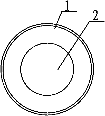
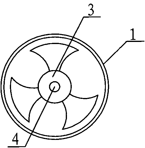
[0031]The cylindrical body 1 of embodiment 1 is made of steel pipe with a diameter of 140 millimeters and a thickness of 3 millimeters, and a length of 450 millimeters. The motor 5 adopts the motor components of the DC submersible pump produced by Zhuhai China Xingye Solar Technology Holdings Co., Ltd. and Zhuhai Xingye New Energy Technology Co., Ltd., the model is: PVP-S12-30D36-0.2, the motor power is 0.2KW, and the working voltage is 36V. Motor 5 also can adopt general AC or DC motor, but waterproof cover will be done well. When using an AC motor, a corresponding power inverter should also be configured when using a DC power supply. Propeller 3 is three blades, 125 millimeters in diameter, casts with steel, and the shaft hole in the middle will cooperate closely with the output shaft 4 of motor 5. Fixed screw rod 6 is made threaded rod with the steel bar of diameter 8 millimeters, and motor 5 is fixed on the central axis of cylinder body 1 through the screw thread on cylin...


PUM


Abstract

The invention relates to a ship propeller which comprises a propeller and is characterized in that the propeller is placed in a cylinder body and closely connected with an output shaft of a motor, the ship propeller further comprises the cylinder body and the motor, and the motor comprises a waterproof outer housing. The ship propeller adopting the measures has compact structure, easy manufacture and low cost; as the motor is arranged underwater, people can not hear obvious noise in a ship on the water surface, thereby being very applicable to manufacturing small cruise ships for leisure sightseeing. The output shaft of the motor is directly connected with the propeller, and the ship propeller has no other indirect transmission parts, so that the power transmission efficiency is very satisfactory.

Description

1. Technical field [0001] The invention belongs to the technical field of electromechanical engineering, in particular to the improvement of a ship propeller. 2. Background technology [0002] Current ship propellers all adopt screw propulsion devices, that is, propellers driven by power machinery or electric motors are used for propulsion. [0003] Application No. 02144864.7, titled "Mechanical Propeller", discloses an invention, which relates to a device capable of generating forward propulsion. One end of the main shaft of this invention is connected with the speed change device, the right crank and the left crank are all fixed on the main shaft, and one end of the right connecting rod and the left connecting rod are respectively hinged with the right crank and the left crank through the right shaft and the left shaft, and the right shaft and The connecting line from the left shaft to the main shaft forms a 180° angle of rotation. The other ends of the right connecting r...

Claims


Application Information

Patent Timeline
Patent Type & Authority Applications(China)
IPC IPC(8): B63H5/07B63H21/17
Inventor 冯岩陈美虞
Owner 冯岩
Why Eureka
Try Eureka