
Heat conductivity coefficient measurer of double-test-piece guarded hot plate for liquid nitrogen temperature area
A thermal conductivity measuring instrument technology, which is applied in the field of thermal conductivity measuring instrument with double specimen protective hot plate in the liquid nitrogen temperature zone, can solve the problems of unsuitable structure and characteristics, thermal conductivity measurement of thermal insulation materials, etc., to reduce liquid nitrogen evaporation, Effect of reducing measurement error
- Summary
- Abstract
- Description
- Claims
- Application Information
AI Technical Summary
Problems solved by technology
Method used
Image

Examples
Embodiment
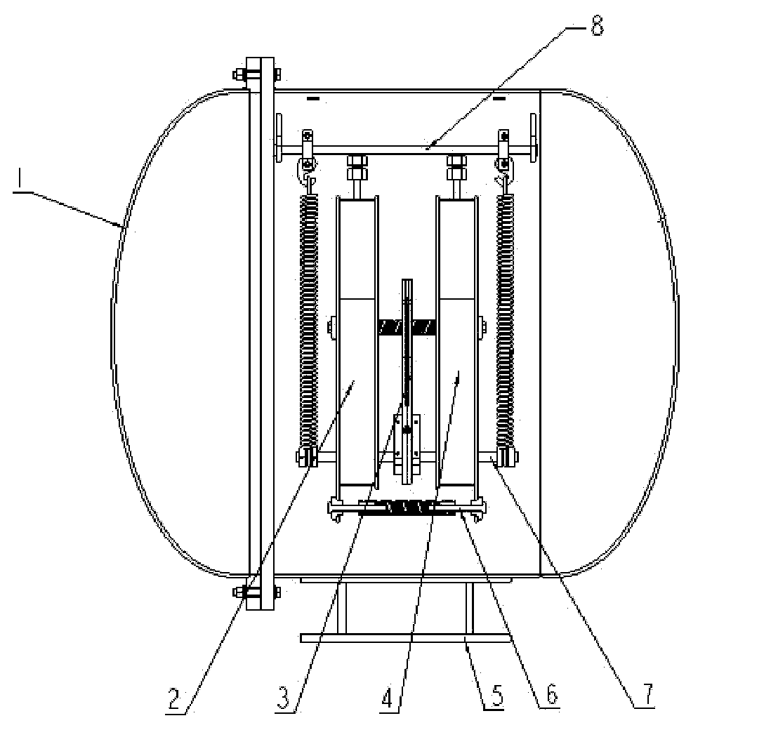
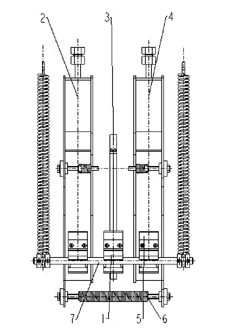
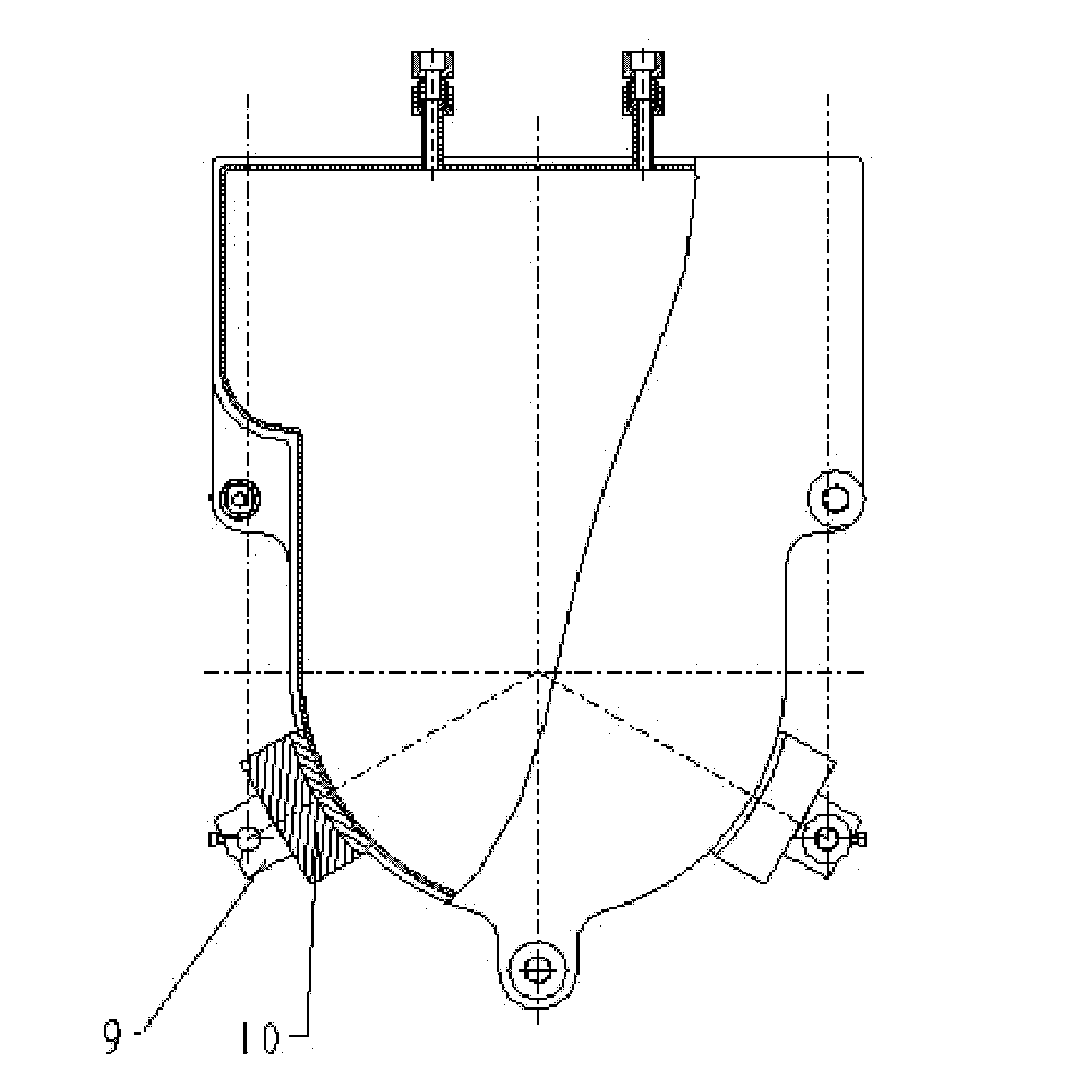
[0022] Such as figure 1 , figure 2 and image 3 As shown, this embodiment includes: a vacuum cover 1, a first liquid nitrogen container 2, a protective hot plate 3, a second liquid nitrogen container 4, two temperature sensors, a support plate 5, a sliding structure 7, a clamping structure 6 and hoisting Structure 8, wherein: the first test specimen is installed between the first liquid nitrogen container 2 and the protective hot plate 3, the second test specimen is installed between the second liquid nitrogen container 4 and the protective hot plate 3, and the protective hot plate 3 is located Between the two liquid nitrogen containers, one end of the clamping structure 6 is set on the first liquid nitrogen container 2, the other end of the clamping structure 6 is set on the second liquid nitrogen container 4, and the liquid nitrogen container and the protective hot plate 3 are fixed on On the sliding structure 7, the sliding structure 7 is connected with the hoisting stru...
PUM
 Abstract
Description
Claims
Application Information