Optical wavelength reflector and manufacture method thereof

A manufacturing method and reflector technology, which is applied in the field of optical fiber manufacturing, can solve the problems of reflection bandwidth drift and high cost, and achieve the effects of stable reflection bandwidth range, low production cost, and concealed and reliable wiring

Inactive Publication Date: 2010-12-15
BROADEX TECH
View PDF5 Cites 9 Cited by
  • Summary
  • Abstract
  • Description
  • Claims
  • Application Information

AI Technical Summary

Problems solved by technology

At present, most of these reflectors are manufactured based on fiber grating technology, which is costly, and the reflection bandwidth will also drift with temperature changes.

Method used


Image

  • Optical wavelength reflector and manufacture method thereof
  • Optical wavelength reflector and manufacture method thereof
  • Optical wavelength reflector and manufacture method thereof

Examples


Embodiment Construction

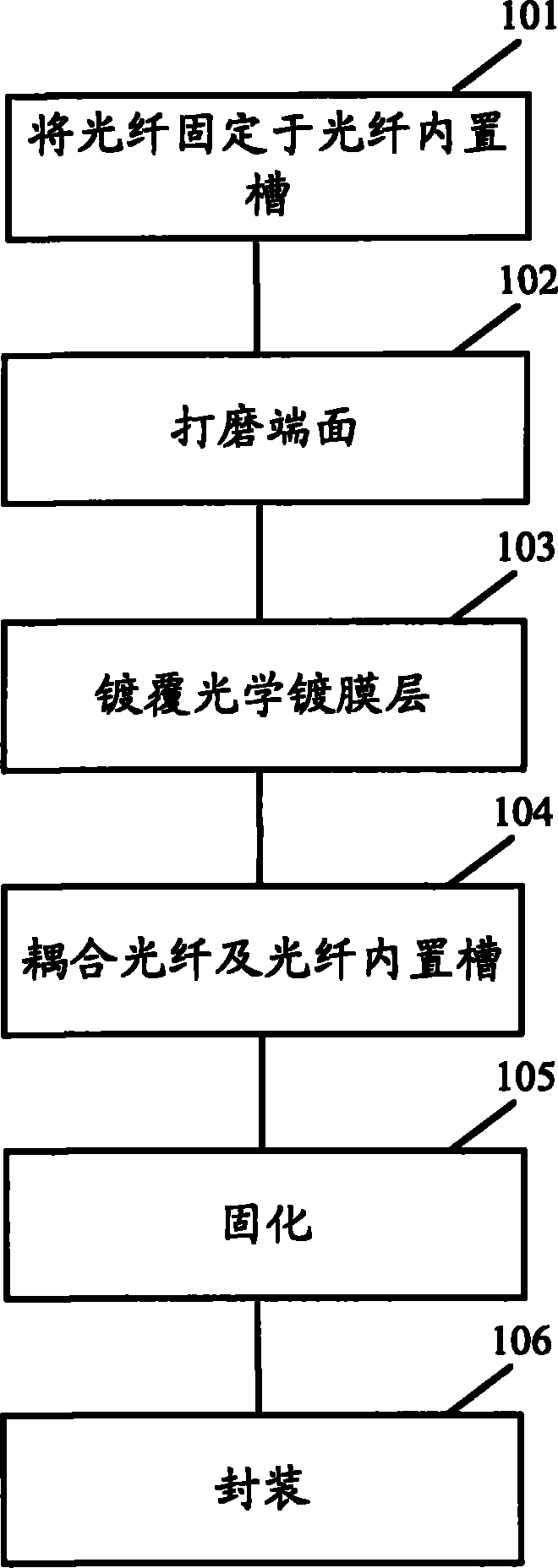
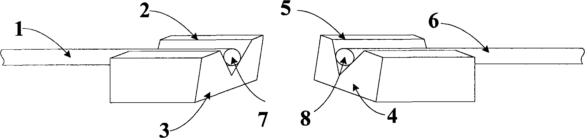
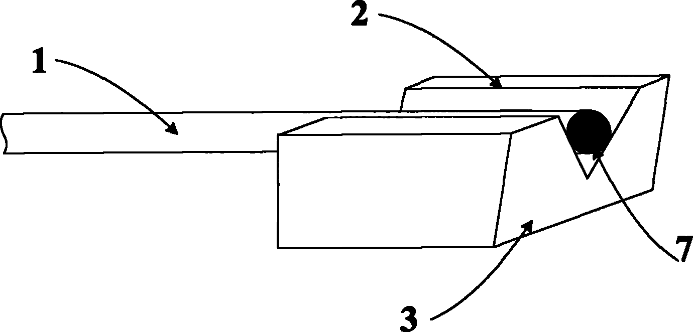
[0025] Embodiments of the present invention will now be described in detail with reference to the accompanying drawings. First, combine Figure 2-5 A first embodiment of the present invention will be described. Figure 5 The finished product of the optical wavelength reflector 10 according to the first embodiment of the present invention is schematically shown. Figure 2 ~ Figure 4 Various stages in the manufacturing process of the optical wavelength reflector 10 are shown. As shown in the figure, the optical wavelength reflector 10 mainly includes a first optical fiber 1, a first optical fiber built-in groove (V-shaped) 2, a second optical fiber 6, a second optical fiber built-in groove (V-shaped) 5, a multilayer optical coating layer and package structure. Such as figure 2 and image 3 As shown, the end face of the first optical fiber 1 and the end face of the first optical fiber built-in groove 2 are polished to a slope with a first inclination angle (for example, 0-1...


PUM


Abstract

The invention provides an optical wavelength reflector which comprises a first optical fiber, a first optical fiber built-in slot, a second optical fiber, a second optical fiber built-in slot, a multi-layer optical coating layer and a packaging structure, wherein the first optical fiber is fixed in the first optical fiber built-in slot; the second optical fiber is fixed in the second optical fiber built-in slot; and the packaging structure is used for packaging an assembly formed by the first optical fiber, the second optical fiber, the first optical fiber built-in slot, the second optical fiber built-in slot and the multi-layer optical coating layer. The invention has the advantages of high temperature stability, low cost, stable reflection bandwidth range, long service life, and the like and can be used for long-term outside work.

Description

technical field [0001] The invention relates to optical fiber manufacturing technology, in particular to an optical wavelength reflector and a manufacturing method thereof. Background technique [0002] When the fiber-to-the-home network detects fiber optic faults, it needs to use an embedded optical wavelength reflector. This optical wavelength reflector is installed in the fiber path at the end of the optical fiber network and can reflect the signal of the fault detection wavelength. The working wavelength can Pass with very little loss (such as less than 1.5dB). At present, most of these reflectors are manufactured based on fiber grating technology, which is costly, and the reflection bandwidth will also drift with the change of temperature. Contents of the invention [0003] Aiming at many deficiencies in the prior art, the present invention aims to provide a low-cost optical fiber path embedded reflector to meet practical application requirements such as fiber fault ...

Claims


Application Information

Patent Timeline
Patent Type & Authority Applications(China)
IPC IPC(8): G02B6/26G02B6/30G02B6/34
Inventor 黄雪钦张更朱伟
Owner BROADEX TECH
Why Eureka
Try Eureka