Photolithography exposure device for implementing off-axis illumination by using free-form surface lens

A curved lens and exposure device technology, applied in the field of lithography, can solve the problems of increasing the complexity of lithography exposure devices

Inactive Publication Date: 2010-12-15
ZHEJIANG UNIV
View PDF5 Cites 18 Cited by
  • Summary
  • Abstract
  • Description
  • Claims
  • Application Information

AI Technical Summary

Problems solved by technology

Similar to the fly-eye lens in the illumination system, to achieve a high uniformity off-axis illumination mode requires the use of a double-row or even multi-row microlens array, and at the same time reduce the size of the microlens, which undoubtedly affects the position of the lithography exposure system. Calibration puts forward higher requirements and also increases the complexity of lithography exposure equipment

Method used


Image

  • Photolithography exposure device for implementing off-axis illumination by using free-form surface lens
  • Photolithography exposure device for implementing off-axis illumination by using free-form surface lens
  • Photolithography exposure device for implementing off-axis illumination by using free-form surface lens

Examples


Embodiment Construction

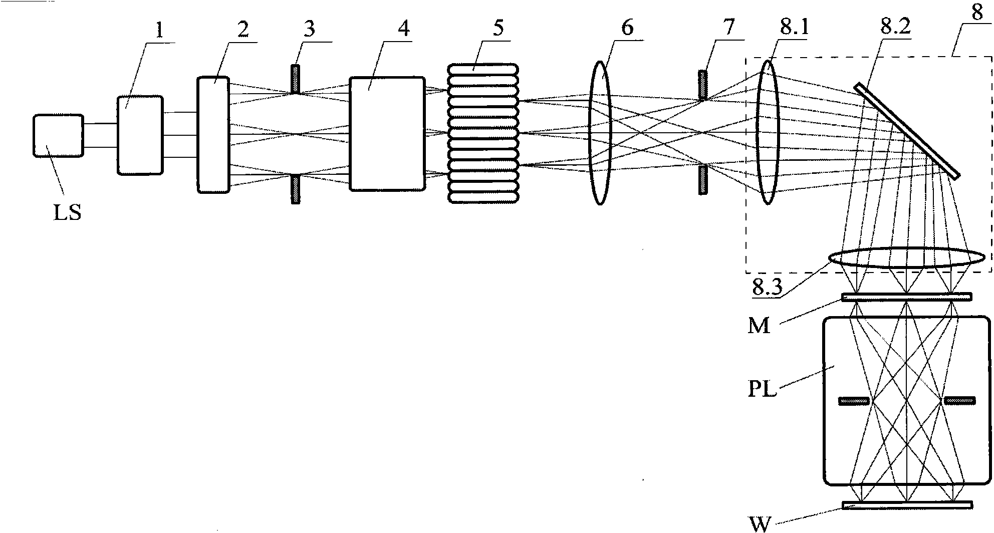
[0053] Such as figure 1 As shown, the lithography exposure device using a free-form surface lens to realize off-axis illumination includes a laser light source LS, a beam expander 1, a free-form surface lens beam shaper 2, a filter diaphragm 3, a zoom optical system 4, an optical integrator 5, Collimation optical system 6, field diaphragm 7, relay optical system 8, mask M, lithography projection objective lens PL, photoresist W; relay optical system 8 includes front lens group 8.1, intermediate mirror 8.2 and rear Lens group 8.3; the outgoing laser beam of the laser light source LS passes through the beam expander 1, the free-form surface lens beam shaper 2, the filter diaphragm 3, the zoom optical system 4, the optical integrator 5, the collimating optical system 6, the field of view Diaphragm 7, relay optical system 8, mask M, lithography projection objective lens PL, and finally irradiated to photoresist W; the position of filter diaphragm 3 and the position of the front su...


PUM


Abstract

The invention discloses a photolithography exposure device for implementing off-axis illumination by using a free-form surface lens. The photolithography exposure device comprises a laser source, a beam expander, a free-form surface lens beam shaper, a filtering diaphragm, a varifocal optical system, an optical integrator, a collimation optical system, a field diaphragm, a relay optical system, a mask, a photolithography projection objective and photoresist, wherein the relay optical system comprises a front lens group, a middle reflection lens and a rear lens group; the position of the filtering diaphragm and the position of the front surface of the optical integrator form a pair of conjugate positions of the varifocal optical system; the position of the rear surface of the optical integrator and the position of the field diaphragm form a pair of conjugate positions of the collimation optical system; the position of the field diaphragm and the position of the mask form a pair of conjugate positions of the relay optical system; and the position of the mask and the position of the photoresist form a pair of conjugate positions of the photolithography projection objective. The photolithography exposure device has the advantages of good shaping effect and high energy utilization rate.

Description

technical field [0001] The invention relates to the technical field of lithography, in particular to a lithography exposure device which adopts a free-form surface lens to realize off-axis illumination. Background technique [0002] Photolithography is a key technology that promotes the rapid development of the semiconductor industry. It replicates the structural pattern of the integrated circuit on the mask to the silicon wafer coated with photoresist through the exposure device and the lithography projection objective lens. In the lithography exposure device, resolution enhancement technology (such as off-axis illumination) can be used to improve the lithography resolution and improve the depth of focus, so the performance of the lithography exposure device determines the performance of the projection lithography system. [0003] A lithography exposure device generally includes several main parts of a beam expander, a beam shaper, a zoom optical system, an optical integrat...

Claims


Application Information

Patent Timeline
Patent Type & Authority Applications(China)
IPC IPC(8): G03F7/20G02B27/09
Inventor 郑臻荣吴仍茂李海峰邢莎莎刘旭
Owner ZHEJIANG UNIV
Why Eureka
Try Eureka