Eureka AIR delivers breakthrough ideas for toughest innovation challenges, trusted by R&D personnel around the world.

Double-sided shear for thick steel plate production and method thereof for automatic plate-shearing for roller way conveying

A technology of double-sided shearing and thick steel plates, which is applied in the field of steel rolling production, can solve problems such as spindle encoder, fan damage, easily damaged shear blades, and drive shaft breakage, so as to prolong equipment life, reduce maintenance costs, and avoid plate punching. Effect

Inactive Publication Date: 2010-12-22
CHONGQING IRON & STEEL (GRP) CO LTD
View PDF6 Cites 20 Cited by
  • Summary
  • Abstract
  • Description
  • Claims
  • Application Information

AI Technical Summary

Problems solved by technology

In addition, when cutting wide, thick, and long steel plates, due to the large inertia of wide, thick, and long steel plates, and the equipment does not have the APC braking function, it is easy to cause unstable plate feeding, which makes the length measuring spindle encoder count repeatedly, resulting in Feeding the board too long will cause the defect of "punching board", which will easily damage the cutting edge, cause shutdown, and seriously affect production efficiency
Due to design reasons, the main faults of the double-sided shears are concentrated on the front and rear pinch rollers, such as broken drive shafts, loose connection seats, and vibrations, resulting in damage to the spindle encoder, fan, etc., resulting in frequent shutdowns and a lot of manpower. Material resources increase production costs. Secondly, frequent failures of the pressure head series also cause frequent shutdowns and affect production efficiency.

Method used


Image

  • Double-sided shear for thick steel plate production and method thereof for automatic plate-shearing for roller way conveying
  • Double-sided shear for thick steel plate production and method thereof for automatic plate-shearing for roller way conveying
  • Double-sided shear for thick steel plate production and method thereof for automatic plate-shearing for roller way conveying

Examples


Embodiment Construction

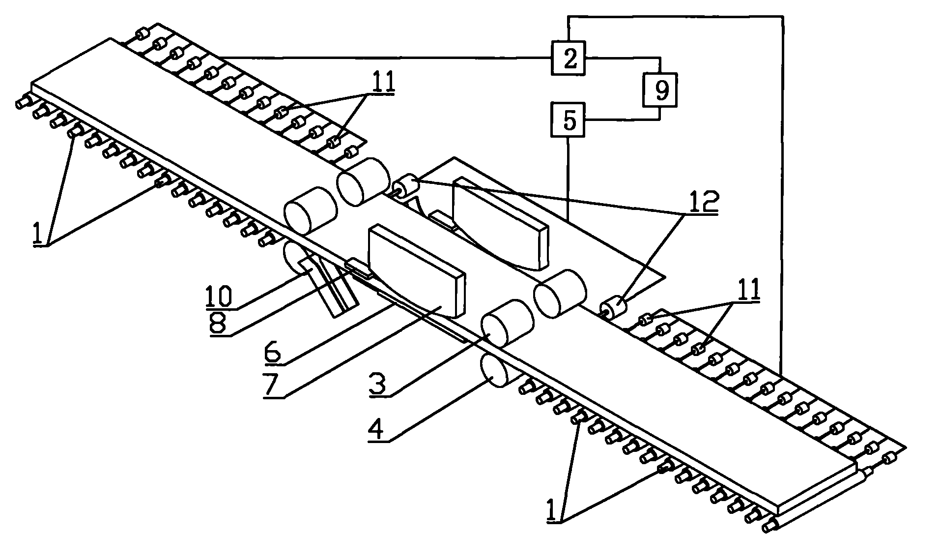
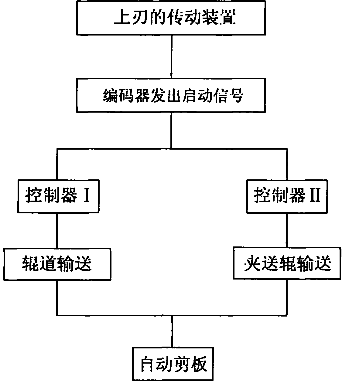
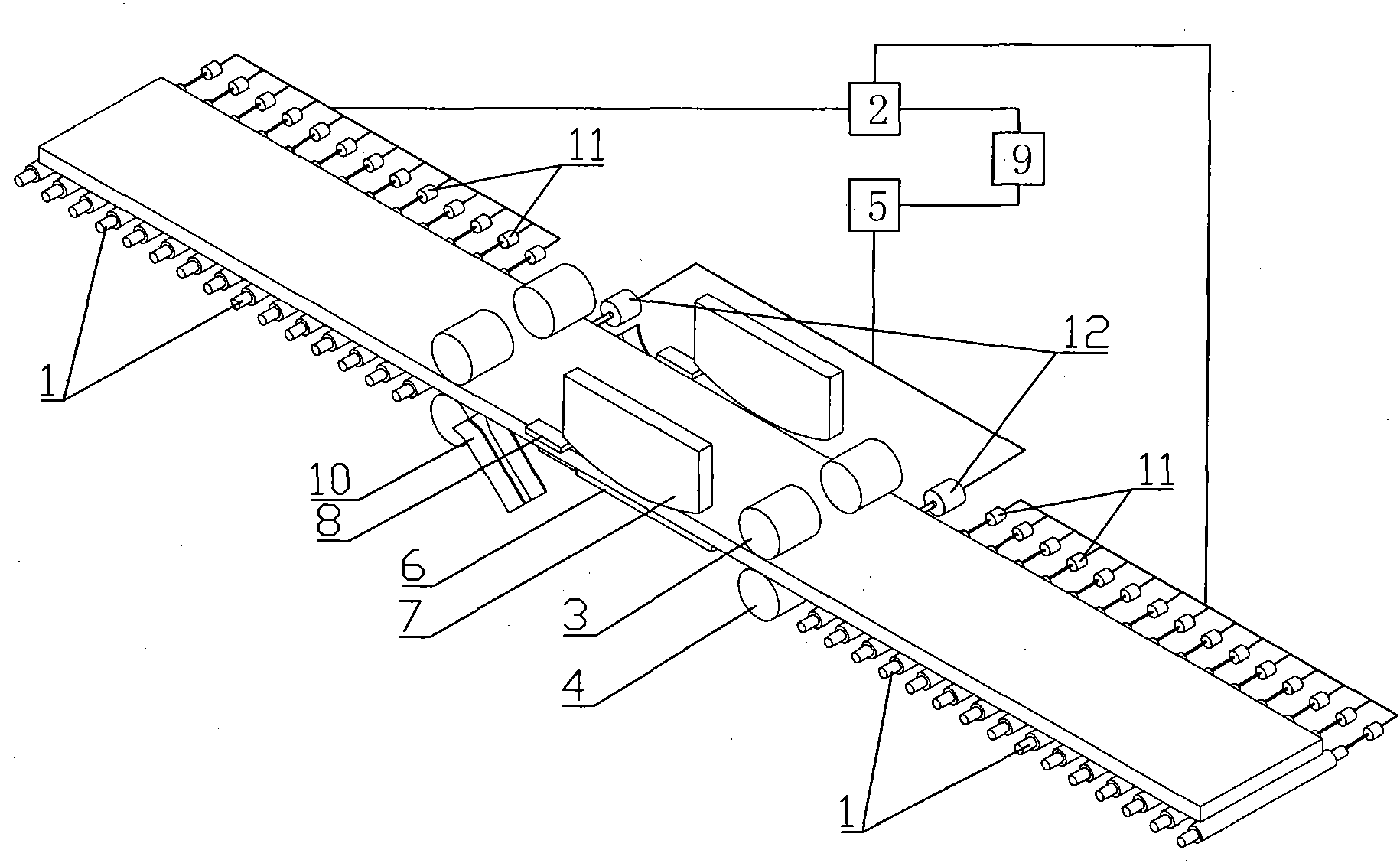
[0016] figure 1 It is the structural representation of double-sided shear of the present invention, figure 2 It is the flow chart of plate feeding control of the plate shearing method of the present invention, as shown in the figure: the double-sided shear for thick steel plate production in this embodiment includes a conveying roller assembly, a pinch roller assembly, a shearing assembly and obliquely arranged waste edges The chute 10, the conveying roller assembly includes the roller table 1 arranged side by side on both sides of the shearing assembly along the steel plate conveying direction, and the roller table drive motor 11 that is matched with the roller table 1 in one-to-one transmission, and is connected with the roller table drive motor 11 A controller I2 capable of delay control is provided; the pinch roller assembly includes two pairs of front pinch rollers and two pairs of rear pinch rollers distributed on both sides of the shear assembly, and the front pinch ro...


PUM


Abstract

The invention discloses a double-side shear for thick steel plate production, which carries out structure improvement of simplifying on a double-side shear device, adopts the movement of a shearing assembly to acquire a starting signal of a conveying motor, and realizes the automatic plate-shearing by the matching of the steel plate conveying and the shearing assembly. By using a shearing method disclosed in the invention to shear a longer steel plate, because the join of a pinch roll assembly is avoided, the stress of the steel plate is even in the process of conveying, and the occurrence of the phenomena of offtrack, plate-throwing and the like are avoided, thereby avoiding the defects of toothpicks, shear bend, shear failure and the like, extremely improving the quality of the steel plate, at the same time, avoiding the faults caused by the join of the pinch roll assembly, improving the production efficiency, prolonging the equipment service life, and reducing the maintenance cost; and in addition, start delay of a motor is set into two gears, whether the steel plate is easy to slip or not is determined by the length of the steel plate, thus the different gears are selected for conveying so as to avoid the phenomenon of impacting the plate.

Description

technical field [0001] The invention relates to the field of steel rolling production, in particular to a double-sided shear for thick steel plate production and an automatic plate shearing method conveyed by a roller table. Background technique [0002] In the finishing operation process in the steel rolling field, the double shear is one of the most critical equipment, and its use will directly affect the smooth progress of the steel rolling production. [0003] In the existing technology, since the feeding of the double-sided shears of the 4100mm thick plate production line is completed by multiple components, its feeding direction is affected by the feeding direction of multiple related parts. In theory, the feeding directions of multiple boards should be consistent to ensure During the dynamic shearing process, the feeding direction does not change before and after, so as to avoid shearing defects caused by phenomena such as "flashing" and "deviation", which affect prod...

Claims


Application Information

Patent Timeline
IPC IPC(8): B23D31/00B23D33/00B23Q7/00
Inventor 曹辉刚景伟
Owner CHONGQING IRON & STEEL (GRP) CO LTD
Why Eureka
Eureka Blog
Learn More