
Clamping device

A clamping device and clamping arm technology, applied in the direction of chuck, manufacturing tool, manipulator, etc., can solve the problems of inconvenient use and maintenance, and achieve the effect of easy use and maintenance and simple structure

Inactive Publication Date: 2010-12-22
HONG FU JIN PRECISION IND (SHENZHEN) CO LTD +1
View PDF9 Cites 40 Cited by
  • Summary
  • Abstract
  • Description
  • Claims
  • Application Information

AI Technical Summary

Problems solved by technology

However, the front end of the existing mechanical arm is usually equipped with pneumatic or hydraulic grippers, which must be equipped with complicated air or oil circuit structures, which is not easy to use and maintain

Method used


Image

  • Clamping device
  • Clamping device
  • Clamping device

Examples


Embodiment Construction

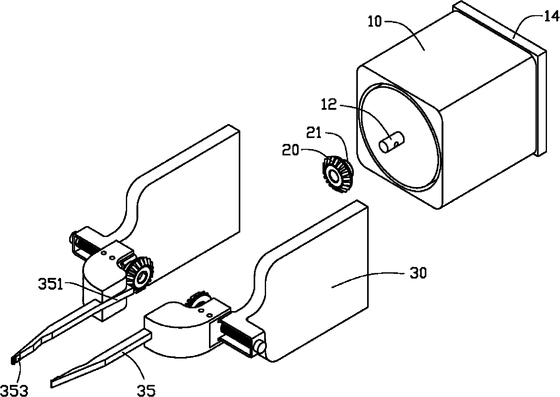
[0011] Please refer to figure 1 , The preferred embodiment of the clamping device of the present invention includes a motor 10 , a driving gear 20 and a pair of clamping bodies 30 .

[0012] A shaft 12 protrudes from a first end of the motor 10 . The second end of the motor 10 (the end away from the first end) is provided with a fixing base 14 .

[0013] The driving gear 20 is a bevel gear, with a mounting portion 21 protruding from its middle toward one end, and the mounting portion 21 is provided with a mounting hole (not shown) along the axial direction.

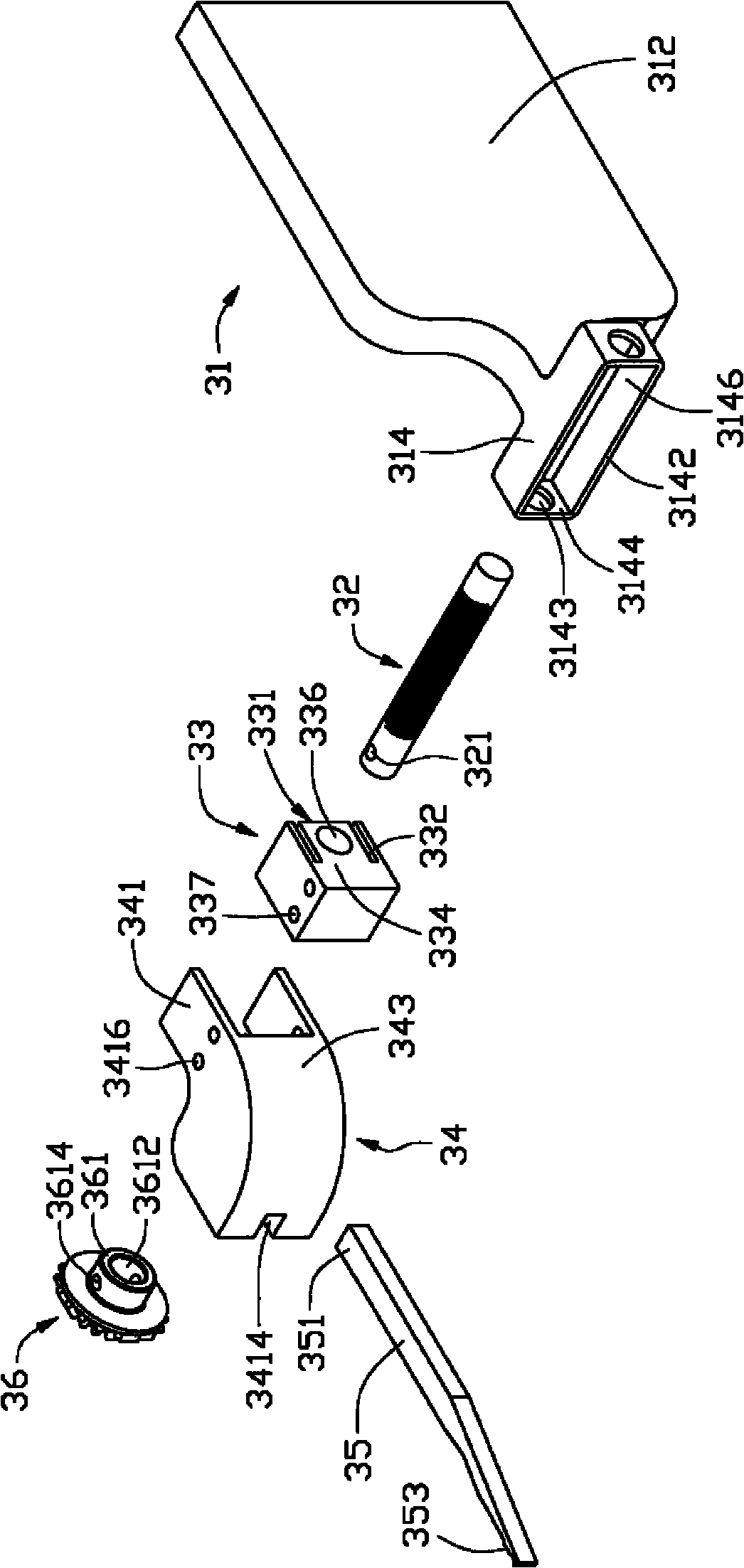
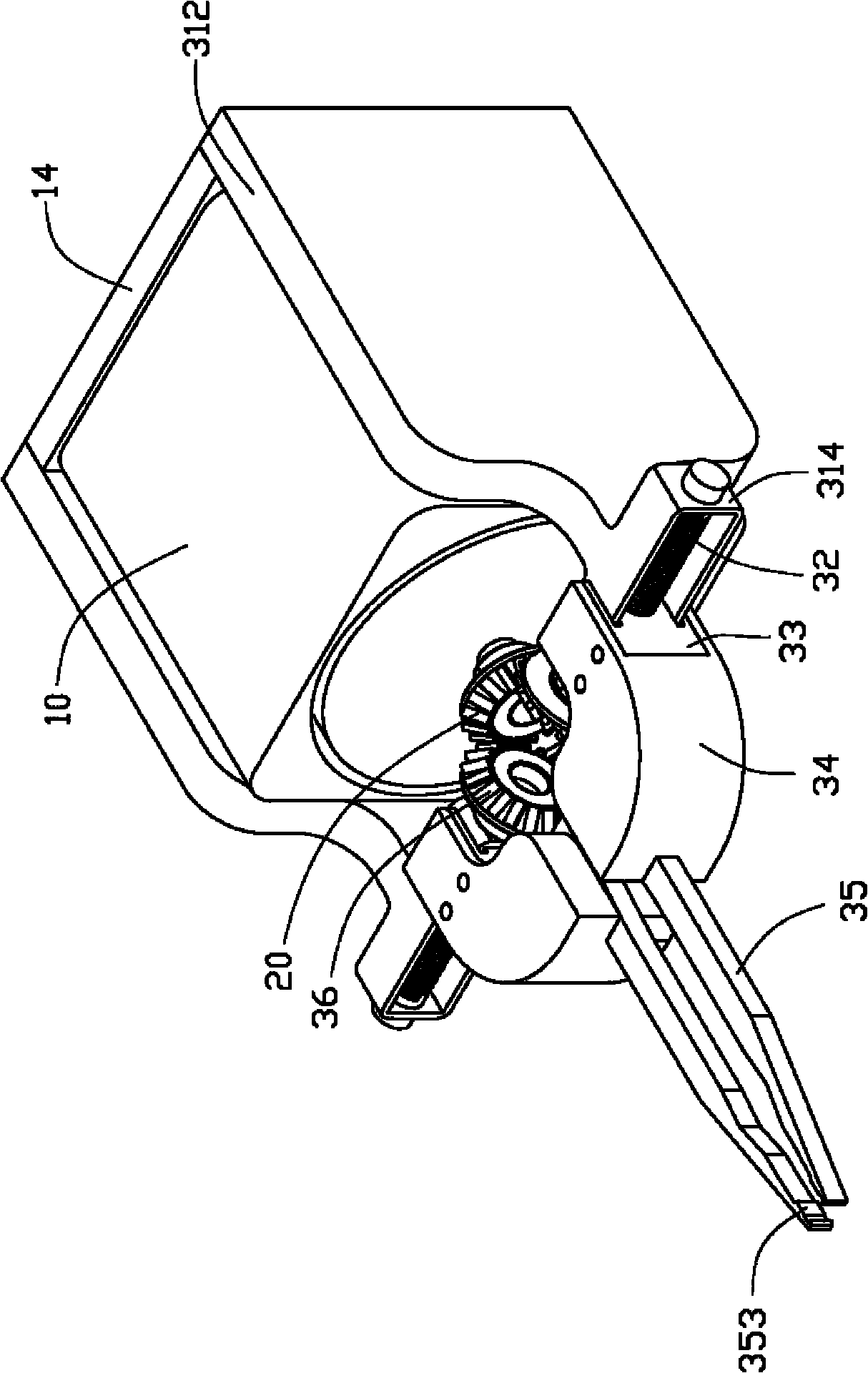
[0014] Please also see figure 2 , the structure and assembly method of the pair of clamping bodies 30 are the same, and only one of them will be taken as an example below for illustration. The clamping body 30 includes a support frame 31 , a screw 32 , a slider 33 , a connecting piece 34 , a clamping arm 35 and a driven gear 36 . The supporting frame 31 includes a side plate 312 and a pivot portion 314 connected to o...


PUM


Abstract

The invention relates to a clamping device used for clamping an object. The clamping device comprises a motor with a rotating shaft, a driving gear arranged on the rotating shaft of the motor and a pair of clamping bodies symmetrically arranged on the motor, wherein each clamping body comprises a driven gear meshed with the driving gear, a screw fixed on the driven gear and rotating with the driven gear, a slider being in thread fit with the screw and a clamp arm fixedly connected with the slider; and the motor rotates to drive the driving gear to rotate, the driving gear drives the driven gear and the screw to rotate, the sliders glide with the rotation of the screws to mutually close or separate, therefore, the object is clamped between the clamp arms or loosened from between the clamp arms. The clamping device has the advantages of simple structure, and convenient use and maintenance.

Description

technical field [0001] The invention relates to a clamping device. Background technique [0002] Robotic arms have been widely used in actual production to replace manual clamping of workpieces or production and testing tools. For example, during the production process of a printed circuit board (PCB), using a robotic arm to hold a test probe and precisely position the test probe on a test portion of the PCB can greatly improve production efficiency and test accuracy. However, the front end of the existing mechanical arm is usually equipped with pneumatic or hydraulic grippers, which must be equipped with complicated air or oil circuit structures, which is not easy to use and maintain. Contents of the invention [0003] In view of the above, it is necessary to provide a clamping device that is simple in structure and easy to use and maintain. [0004] A clamping device for clamping an object, the clamping device includes a motor with a rotating shaft, a driving gear moun...

Claims


Application Information

Patent Timeline
Patent Type & Authority Applications(China)
IPC IPC(8): B25J15/00
CPCB25J15/026
Inventor 李昇军许寿国
Owner HONG FU JIN PRECISION IND (SHENZHEN) CO LTD
Learn More