Method for controlling radial clearance leakage loss of turbomachine
A technology of radial clearance and impeller machinery, applied in the direction of leakage prevention, mechanical equipment, engine components, etc., can solve the problems of increased total weight of impeller machinery, decreased aerodynamic performance of blade shape, limited effect, etc., and reduces production and use costs , the effect of suppressing the formation of leakage flow and the generation of leakage vortex
- Summary
- Abstract
- Description
- Claims
- Application Information
AI Technical Summary
Problems solved by technology
Method used
Image
Examples
Embodiment 1
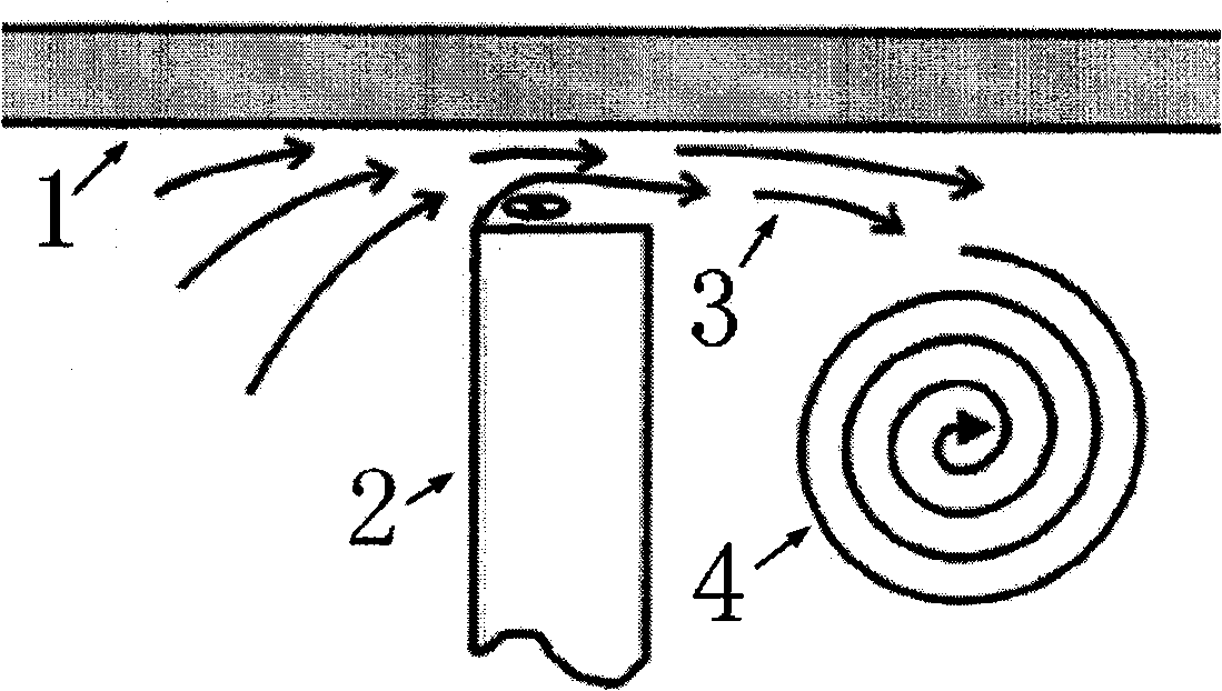
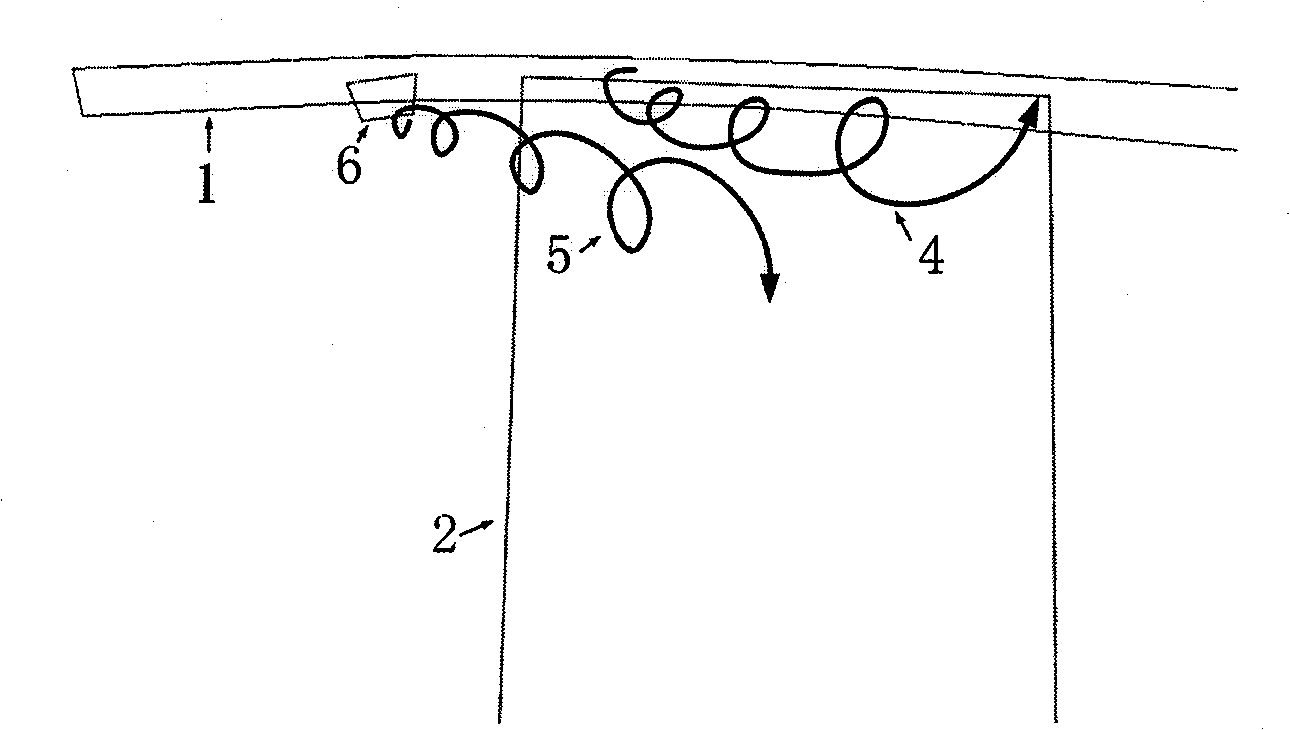
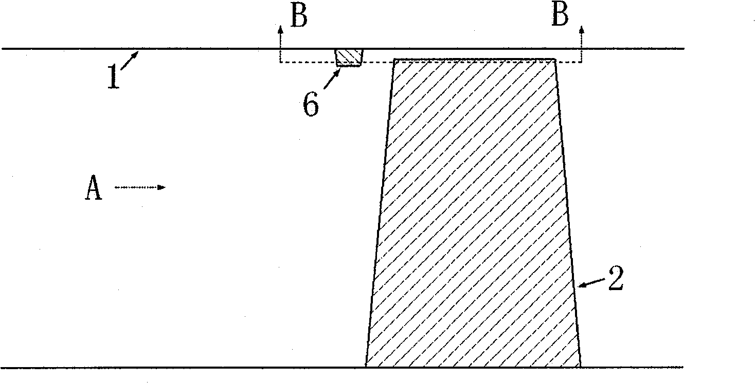
[0024] Embodiment 1: Retrofitting the flow channel end wall 1 near the front edge of the rotor. Since the intensity of the turbine leakage flow belongs to the middle level, the structure of the leakage vortex 4 also belongs to the middle level of complexity. After preliminary numerical simulation and experiment, a row of spoilers 6 is arranged on the upstream of the rotating blade 2, the number of which is the same as that of the rotating blade 2. When the quantity is the same, better results can be obtained, and the loss of leakage flow is controlled within a smaller range. Spoilers 6 are placed axially at a position of 5.0% of the axial chord length upstream of the rotating blade 2, and are distributed at equal intervals in the circumferential direction. The spoiler 6 is an isosceles trapezoid, and its structure and installation schematic diagram are shown in Figure 3-5 . The lengths of the upper and lower ends of the spoiler 6 are 5mm and 4mm respectively, which are 5.0%...
Embodiment 2
[0025] Embodiment 2: For the turbine of Embodiment 1, in order to expand the action area and scale coverage of the vortex 5 and further improve its suppression of the leakage vortex 4, the following methods can be adopted to obtain a better control effect. The flow channel end wall 1 near the leading edge of the rotor is modified, and two rows of spoilers 6 are axially arranged upstream of the rotating blade 2 . Both rows of spoilers 6 are isosceles trapezoidal, and its structure and installation schematic diagram are shown in Figure 6 and Figure 7 . The first row of spoilers 6 is placed axially at a position of 6.0% of the chord length upstream of the rotating blade 2 , and the second row of spoiler 6 is placed axially at a position of 3.0% of the chord length of the upstream of the rotating blade 2 . All spoilers 6 form an included angle of 10° with the incoming flow direction. In order to reduce the flow loss caused by the spoiler 6 itself, the front and trailing edges...
PUM
 Abstract
Description
Claims
Application Information
 - R&D
- Intellectual Property
- Life Sciences
- Materials
- Tech Scout
- Unparalleled Data Quality
- Higher Quality Content
- 60% Fewer Hallucinations
Browse by: Latest US Patents, China's latest patents, Technical Efficacy Thesaurus, Application Domain, Technology Topic, Popular Technical Reports.
© 2025 PatSnap. All rights reserved.Legal|Privacy policy|Modern Slavery Act Transparency Statement|Sitemap|About US| Contact US: help@patsnap.com


