
Method and system for calibrating laser scanner

A laser scanner, scanner technology, applied in radio wave measurement systems, instruments, etc., can solve the problems of large manual workload and difficult actual operation.

Active Publication Date: 2010-12-22
CAPITAL NORMAL UNIVERSITY
View PDF4 Cites 36 Cited by
  • Summary
  • Abstract
  • Description
  • Claims
  • Application Information

AI Technical Summary

Problems solved by technology

[0013] The purpose of the present invention is to overcome the shortcomings of the traditional laser scanner calibration method, which has a large manual workload and difficult actual operation (requires the cooperation of many people), and provides a method that can automatically perform the calibration process and process without manual intervention. Calibration method of laser scanner for realizing high-precision calibration and calibration system for realizing the method

Method used


Image

  • Method and system for calibrating laser scanner
  • Method and system for calibrating laser scanner
  • Method and system for calibrating laser scanner

Examples


Embodiment Construction

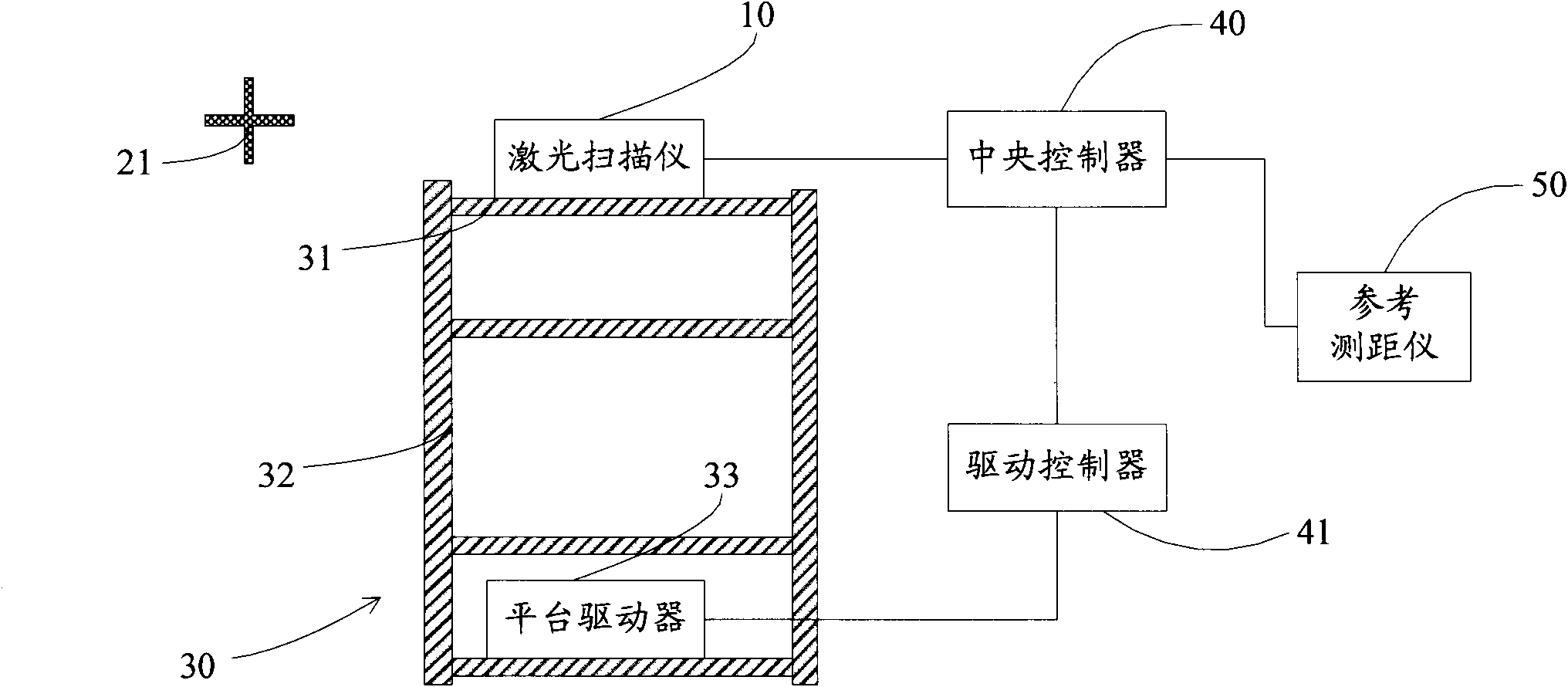
[0047] The present invention will be described in detail below in conjunction with the accompanying drawings. first reference figure 2 , which is a schematic diagram of the composition and structure of an embodiment of the laser scanner calibration system of the present invention. Wherein, the laser scanner 10 is located on the controllable precision lifting platform 30, and can be raised and lowered together with the lifting platform, and the lifting platform is driven by its platform driver to move up and down. A plurality of marker points 21 are arranged around the laser scanner, and the number of marker points should at least meet the requirement of identifying the parameters of the coordinate transformation matrix between the instrument coordinates of the laser scanner and the local coordinates of the reference rangefinder. On this basis, the position and distribution of the marker points can be flexibly designed according to the different emphases of the error categori...


PUM


Abstract

The invention relates to a method and a system for calibrating a laser scanner. A plurality of marking points are distributed in a working area of the laser scanner; the laser scanner is controlled to lift at a constant speed along the axis vertical to the scanning direction, and the working area is measured and imaged; local coordinates of the scanning center of the laser scanner before and after the lifting are acquired by a reference ranger; local coordinates of the marking points are acquired by the reference ranger; marking points in the point cloud of the laser scanner and instrument coordinates thereof are identified, and the scanning time for the marking points is extracted; the local coordinates of the center of the laser scanner are calculated according to the scanning time for the marking points, and a conversion relationship from an instrument coordinate system to a local coordinate system is solved. Therefore, the method and the system overcome the defect of instability caused by artificial participation in controlling target pole movement in the traditional mode, and acquire high-precision calibration results.

Description

technical field [0001] The present invention relates to a laser scanner, especially a two-dimensional laser scanner based on line scanning for distance measurement; more specifically, the present invention relates to a method for calibrating the scanner to determine its internal error, and A calibration system for implementing the method. It belongs to the technical field of remote sensing earth observation and geographic information system construction. Background technique [0002] The main purpose of the calibration of the laser scanner is to verify whether its performance meets the nominal technical indicators, and to compensate for the systematic errors found during the calibration process. And identify scanners whose system errors are too large to be tolerated or cannot be corrected by compensation. [0003] Due to the characteristics of the working principle of the line-scanning laser scanner, it cannot accurately image a specific point but can only scan "line-by-li...

Claims


Application Information

Patent Timeline
IPC IPC(8): G01S7/497
Inventor 宫辉力王留召钟若飞刘先林
Owner CAPITAL NORMAL UNIVERSITY
Features
  • Generate Ideas
  • Intellectual Property
  • Life Sciences
  • Materials
  • Tech Scout
  • Unparalleled Data Quality
  • Higher Quality Content
  • 60% Fewer Hallucinations
Learn More