Positioning method based on infrared light spots

An infrared light and point positioning technology, applied in the field of positioning, can solve the problems of increased power consumption of mobile control equipment, increased product cost, etc., and achieve the effects of benefiting power consumption control and cost control, reducing power consumption, and reducing information processing capacity

Inactive Publication Date: 2010-12-22
鼎亿数码科技(上海)有限公司 +1
View PDF0 Cites 10 Cited by
  • Summary
  • Abstract
  • Description
  • Claims
  • Application Information

AI Technical Summary

Problems solved by technology

The disadvantage of this method is that because the optical sensor is placed on the mobile control device (such as a remote control, game handle, etc.), complex signal processing processes such as positioning algorithms and signal processing need to be performed on the mobile control device, and the mobile control device needs to have a powerful Signal processing and analysis modules, on the one hand, this increases the product cost of mobile control equipment, and on the other hand, increases the power consumption of mobile control equipment

Method used


Image

  • Positioning method based on infrared light spots
  • Positioning method based on infrared light spots
  • Positioning method based on infrared light spots

Examples


Embodiment 1

[0058] The specific process of embodiment one is as follows Figure 4 shown.

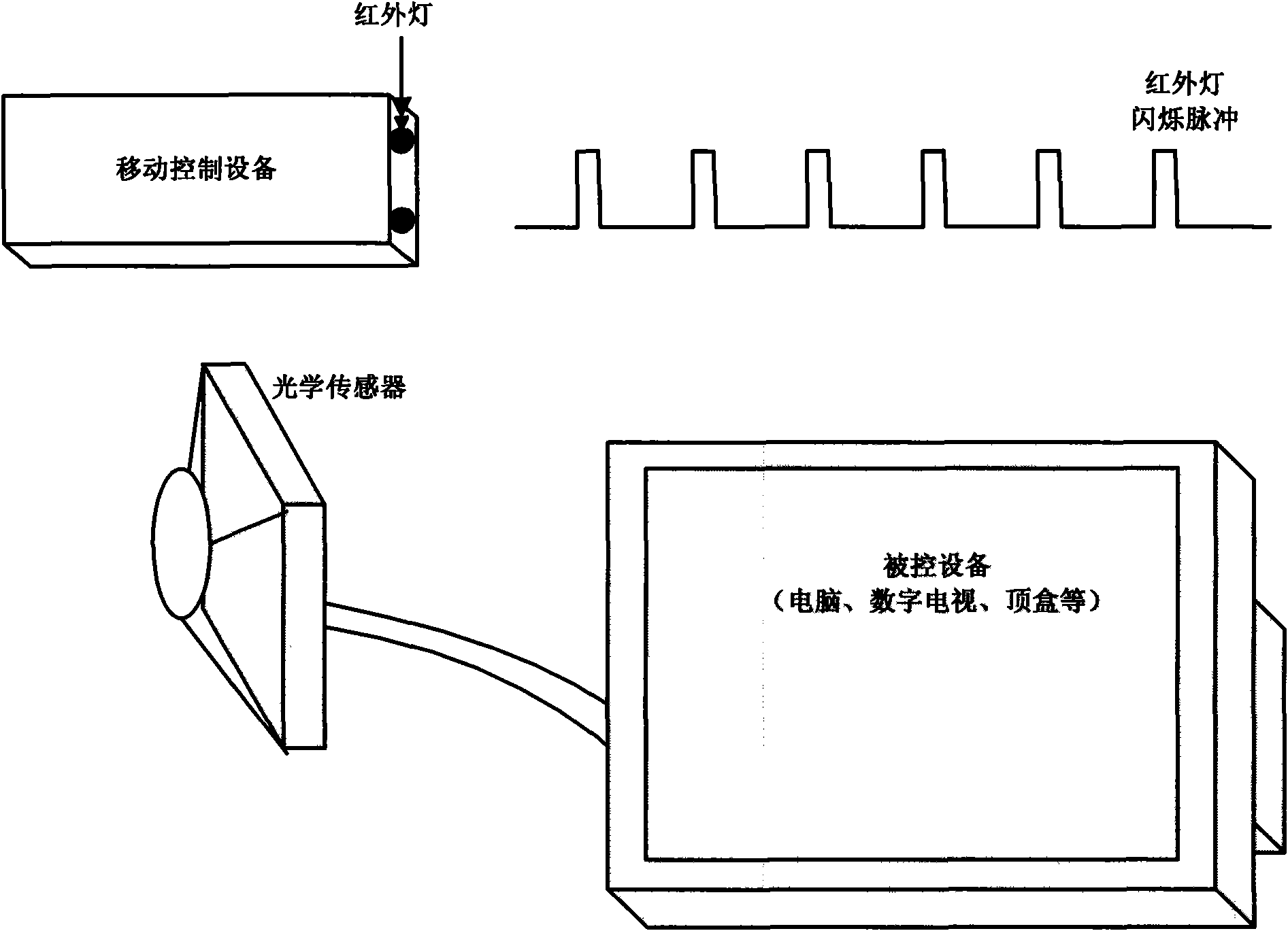
[0059] Optical sensor controlled device side:

[0060] 1. The optical sensor connected to the controlled device scans the external infrared light spots at a fixed scanning speed (for example, 300 frames per second);

[0061] 2. Determine whether any infrared light spots are scanned, if not, proceed to the next scan, if found infrared light spots, go to step 3;

[0062] 3. Analyze the size and shape of the infrared light spots. The infrared light spots that meet the conditions are retained as effective infrared light spots, and the infrared light spots that do not meet the conditions are filtered out. In order to prevent other external interference light sources from adversely affecting the positioning;

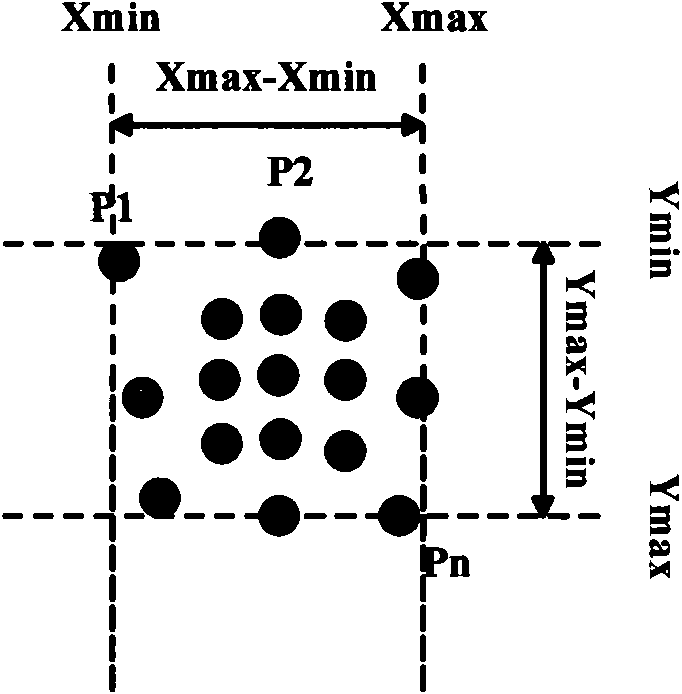
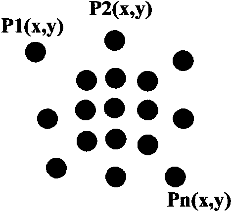
[0063] 4. Calculate the plane positioning position of the infrared light point (for the case of multiple infrared light points, the distance between the infrared light points should also be calcu...

Embodiment 2

[0070] The concrete process of embodiment two is as follows Figure 5 shown.

[0071] Optical sensor controlled object side:

[0072] 1. The optical sensor scans the external infrared light spot at its fastest scanning speed (for example: 500 frames per second), such as Figure 7 shown;

[0073] 2. Calculate the frequency of the infrared light switch, the specific time of turning on and off through the obtained external infrared light flashing information;

[0074] 3. Adjust the scanning frequency of the optical sensor to be the same as the switching frequency of the infrared light, and make sure that the start time of scanning is when the infrared light is turned on and turned on steadily (for example: if the time for the infrared light to be turned on is divided into 3T equal parts, the scanning time is at the infrared about 1 / 3T after the light is on);

[0075] 4. The optical sensor scans according to the adjusted scanning start time and scanning frequency;

[0076] 5....


PUM


Abstract

The invention discloses a positioning method based on infrared light spots. In the positioning method, by arranging an infrared lamp on mobile control equipment and an optical sensor on a controlled equipment end, the motion of the mobile control equipment enables the infrared light spots of the infrared lamp to move in space, and the optical sensor acquires infrared light spot data and then sends to controlled equipment for processing so as to realize positioning, therefore the information processing amount of a mobile control equipment end is greatly reduced so as to be beneficial to the power consumption control and the cost control of the mobile control equipment; by turning on and turning off the infrared lamp arranged on the mobile control equipment according to certain frequency intermittence, the optical sensor arranged on the controlled equipment end acquires the infrared light spots by adopting scanning frequency matched with the switching frequency of the infrared lamp, therefore the requirements for the positioning can be better ensured, and power consumption generated due to the infrared lamp is reduced.

Description

technical field [0001] The invention relates to positioning technology, in particular to a positioning method based on infrared light points. Background technique [0002] With the development of digital TV technology, the combination of computer and TV is getting closer and closer. A digital TV also includes computer content, for example, you can surf the Internet to browse news, play games and so on. The traditional TV remote control is far from meeting the needs of functional control. [0003] With the development of new sensors and positioning methods, air positioning methods based on different principles were born. For example, spatial positioning based on gyroscope and acceleration sensor, cursor positioning based on joystick movement, and so on. [0004] Positioning by infrared light at the imaging position of the optical sensing component is a relatively new positioning method that is currently appearing, and is widely used in the positioning of the computer mouse ...

Claims


Application Information

Patent Timeline
Patent Type & Authority Applications(China)
IPC IPC(8): G06F3/033
Inventor 喻应东
Owner 鼎亿数码科技(上海)有限公司
Why Eureka
Try Eureka