
Maximum power factor control method of intermediate frequency power supply induction heating apparatus

A technology of induction heating device and intermediate frequency power supply, which is applied in the direction of induction heating control, induction heating, etc., and can solve the problems of increased coil temperature rise, reduced heating efficiency, waste, etc.

Inactive Publication Date: 2010-12-22
湘潭科创机电有限公司
View PDF3 Cites 7 Cited by
  • Summary
  • Abstract
  • Description
  • Claims
  • Application Information

AI Technical Summary

Problems solved by technology

Part of the energy is wasted on the energy storage element (mainly the coil), which increases the temperature rise of the coil, reduces the heating efficiency, and sometimes cannot even meet the requirements of the production process
The traditional power factor control method generally uses a phase-locked loop to track the resonant frequency, and synchronously samples the voltage at both ends of the coil and the zero-crossing point of the flowing current to obtain the real-time power factor of the system. However, due to the direct sampling of voltage and current, It is very difficult to track when the current waveform or voltage waveform is not a sine wave, and the current and voltage waveforms are often relatively poor in the operation of the intermediate frequency power supply, so the traditional phase-locked loop control power factor control can only achieve about 90%.

Method used


Image

  • Maximum power factor control method of intermediate frequency power supply induction heating apparatus
  • Maximum power factor control method of intermediate frequency power supply induction heating apparatus
  • Maximum power factor control method of intermediate frequency power supply induction heating apparatus

Examples


Embodiment Construction

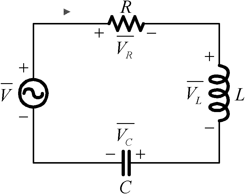
[0014] The following is an R-L-C series resonant circuit to illustrate the principle of the power factor control method. The system principle is as follows: figure 1 As shown in the figure, R, L, and C are the resistance, inductance, and capacitance of the power resonant circuit respectively. The system resonant frequency is determined by the inductance and capacitance of the resonant circuit, as shown in the following formula:

[0015] When the circuit resonates (X L =X C ):

[0016]

[0017] When f<f0, reactance XL<XC, the circuit is capacitive.

[0018] When f = f0, reactance XL = XC, the circuit is resistive. At the time of resonance, the circuit impedance Z0=R is the minimum and produces the maximum current.

[0019] When f>f0, reactance XL>XC, the circuit is capacitive

[0020] Where f is the output frequency of the intermediate frequency power supply, XL is the system inductive reactance, and XC is the system capacitive reactance.

[0021] It can be seen that...


PUM


Abstract

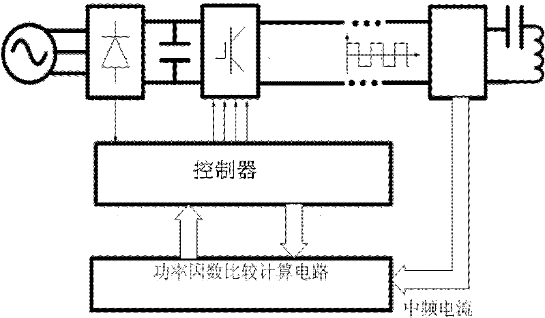
The invention discloses a maximum power factor control method of an intermediate frequency power supply induction heating apparatus. The method has the following steps: a current transformer is used to measure intermediate frequency power supply current; a controller controls impulse by a power inverter to calculate intermediate frequency power supply voltage; phase comparison is carried out on the intermediate frequency power supply current and intermediate frequency power supply voltage and the intermediate frequency power supply power factor is calculated; the controller controls the frequency of the intermediate frequency power supply induction heating apparatus according to the power factor to enable the intermediate frequency power supply induction heating apparatus to maintain the maximum power factor. In the invention, the intermediate frequency power supply induction heating apparatus can maintain the maximum power factor which normally can reach more than 97%.

Description

technical field [0001] The invention relates to an induction heating device for an intermediate frequency power supply, in particular to a method for controlling the maximum power factor of the induction heating device for an intermediate frequency power supply. Background technique [0002] In the medium frequency induction heating process, the main parameter reflecting the heating efficiency of induction heating is the power factor. The power factor has a lot to do with the material of the heated workpiece. During the heating process of metal, its magnetic permeability, inductance and electrical conductivity will all change, which will affect the change of resonance frequency. When the frequency of the external excitation power is consistent with the resonant frequency of the system itself, the current and voltage are in phase, and the power factor reaches the maximum value. When the characteristics of the heated workpiece such as material, shape, size, temperature, etc....

Claims


Application Information

Patent Timeline
IPC IPC(8): H05B6/06
Inventor 蔡罗强杨柏辉
Owner 湘潭科创机电有限公司
Learn More