Medical heat exchanger, manufacturing method thereof and artificial lung device

A heat exchanger and medical technology, which is applied in the direction of suction equipment, dialysis system, blood circulation treatment, etc., can solve the problems of greater influence of flow rate and lower heat exchange efficiency

Inactive Publication Date: 2013-01-16
JMS CO LTD
View PDF1 Cites 0 Cited by
  • Summary
  • Abstract
  • Description
  • Claims
  • Application Information

AI Technical Summary

Problems solved by technology

As a result, it was found that the flow velocity of the cold and hot water flowing through the inner cavity of the thin heat transfer tube 101 has a large influence as the cause of the decrease in the heat exchange efficiency.

Method used


Image

  • Medical heat exchanger, manufacturing method thereof and artificial lung device
  • Medical heat exchanger, manufacturing method thereof and artificial lung device
  • Medical heat exchanger, manufacturing method thereof and artificial lung device

Examples


Embodiment approach 1

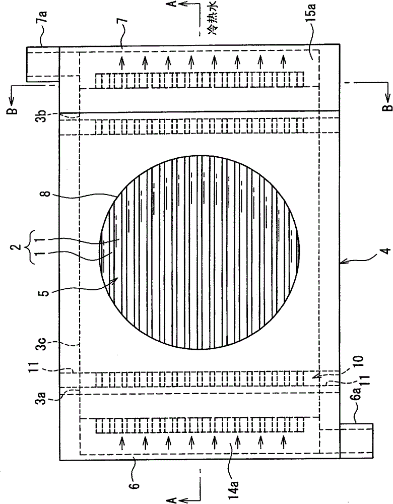
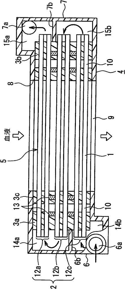
[0084] Figure 1A It is a plan view showing the medical heat exchanger according to Embodiment 1. Figure 1B yes Figure 1A A-A sectional view of, Figure 1C yes Figure 1A The B-B section view. This heat exchanger is provided with: a thin tube bundle 2, which is composed of a plurality of heat transfer thin tubes 1 for circulating a heat medium liquid, that is, hot and cold water; sealing members 3a to 3c, which seal the thin tube bundle 2; and a housing 4 for housing the above-mentioned members. .

[0085] A plurality of thin heat transfer tubes 1 are arranged and stacked in parallel to form a thin tube bundle 2 , and cold and hot water flow in the inner cavity of each thin heat transfer tube 1 . A blood flow channel 5 having a circular cross section is formed in the longitudinal center of the thin tube bundle 2 of the center sealing member 3c, and functions as a heat exchange region for circulating blood, which is a liquid to be heat exchanged. The blood passing throu...

Embodiment approach 2

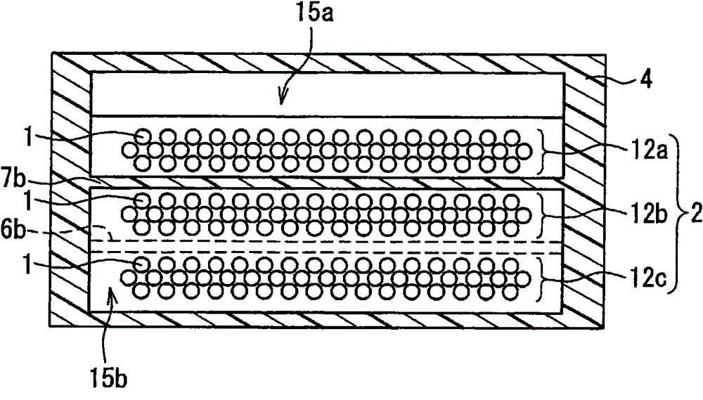
[0107] Same as Embodiment 1, refer to Figure 1A ~ Figure 1C A medical heat exchanger according to Embodiment 2 will be described. This embodiment is a case where a plurality of thin tube bundle units are laminated in the blood flow direction, that is, in the longitudinal direction, and has a longitudinally folded structure, and is used as a member for forming spaces between the respective stages of the first to third thin tube bundle units 12a to 12c. The structure of the spacer 13 will be described in detail. The other structures are the same as those in Embodiment 1, and repeated descriptions are omitted.

[0108] As described in the description of Embodiment 1, in order to form a longitudinal folding structure, the flow chamber for introducing cold and hot water into the header 6 needs to be divided into the upper flow compartment 14a and the lower flow compartment 14b through the partition wall 6b, and the cold and hot water must be separated through the partition wall 7...

Embodiment approach 3

[0116] Figure 7A It is a plan view showing the medical heat exchanger according to Embodiment 3. Figure 7B yes Figure 7A C-C section view. Figure 7A The shape of the D-D section is with Figure 1C The same applies to the first embodiment shown. This embodiment is characterized in that, as Figure 7B As shown, the insertion member 20 is disposed between the respective stages of the first to third capillary bundle units 12 a to 12 c in the blood flow channel 5 . Therefore, the same reference numerals are assigned to the same elements as those in the first and second embodiments, and redundant descriptions will be omitted.

[0117] As described in Embodiment 2, if spacers 13 are installed between the multi-stage narrow tube bundle units 12a to 12c to form intervals of a predetermined length between each stage, it is possible to sequentially distribute hot and cold water in a desired order. By the simple structure of each thin tube bundle unit 12a-12c. When using this s...


PUM


Abstract

A medical heat exchanger includes a thin tube bundle 2 in which a plurality of heat transfer thin tubes 1 for letting heat medium liquid flow therethrough are arranged and stacked, seal members 3a to 3c sealing the thin tube bundle while allowing both ends of the heat transfer thin tubes to be exposed and forming a blood channel 5 which allows blood to flow therethrough so that the blood comes into contact with each outer surface of the heat transfer thin tubes; a housing 4 containing the seal members and the thin tube bundle and provided with an inlet port 8 and an outlet port 9 of the blood positioned respectively at both ends of the blood channel; and a pair of heat transfer thin tube headers 6, 7 forming flow chambers 14a, 14b, 15a, 15b that respectively surround both ends of the thin tube bundle and having an inlet port 6a and an outlet port 7a of the heat medium liquid. The thin tube bundle is divided into a plurality of thin tube bundle units 12a to 12c, and the heat transfer thin tube headers are configured so that the heat medium liquid passes through the plurality of the thin tube bundle units successively. Heat exchange efficiency is enhanced while the flow speed of the heat medium liquid flowing through the heat transfer thin tubes is increased to suppress the increase in volume of the blood channel.

Description

technical field [0001] The present invention relates to a heat exchanger, in particular to a medical heat exchanger suitable for use in medical equipment such as an artificial lung device, a method for manufacturing the same, and an artificial lung device provided with the heat exchanger. Background technique [0002] In cardiac surgery, the patient's heart is stopped, and an artificial heart-lung device is used to perform breathing and circulation functions during this period. Moreover, in order to reduce the patient's oxygen consumption during the operation, it is necessary to lower the patient's body temperature and maintain it. Therefore, the artificial heart-lung apparatus is equipped with a heat exchanger for controlling the temperature of the blood taken from the patient. [0003] As such a medical heat exchanger, a bellows type heat exchanger or a multi-tube type heat exchanger is conventionally known (for example, refer to Patent Document 1). Among them, if the de...

Claims


Application Information

Patent Timeline
Patent Type & Authority Patents(China)
IPC IPC(8): A61M1/36A61M1/14
CPCA61M2001/1629A61M1/1698A61M1/369A61M1/1629A61M1/3623
Inventor 中尾彰多新妻友和泉田秀树
Owner JMS CO LTD
Why Eureka
Try Eureka