Antenna structure and wireless communication device equipped with the same

An antenna structure and antenna technology, which are applied to antenna supports/installation devices, mid-position feeding between antenna terminals, and antennas, etc., can solve the problems of difficult design and increase in antenna manufacturing costs, and achieve sufficient length and increase in length. Loop diameter, cost reduction effect

Inactive Publication Date: 2010-12-22
MURATA MFG CO LTD
View PDF3 Cites 1 Cited by
  • Summary
  • Abstract
  • Description
  • Claims
  • Application Information

AI Technical Summary

Problems solved by technology

However, in the antenna structures proposed in the past, it is difficult to realize the design when the metal part is located on the back side of the antenna.
In addition, if the corresponding antennas are respectively configured according to various models, the manufacturing cost of the antennas will increase, which is not desirable.

Method used


Image

  • Antenna structure and wireless communication device equipped with the same
  • Antenna structure and wireless communication device equipped with the same
  • Antenna structure and wireless communication device equipped with the same

Examples


Embodiment Construction

[0044] Hereinafter, embodiments according to the present invention will be described based on the drawings.

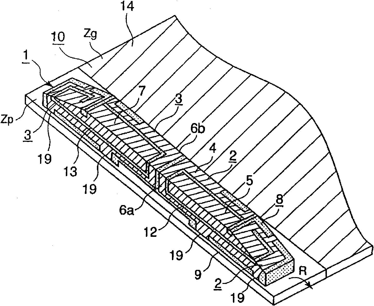
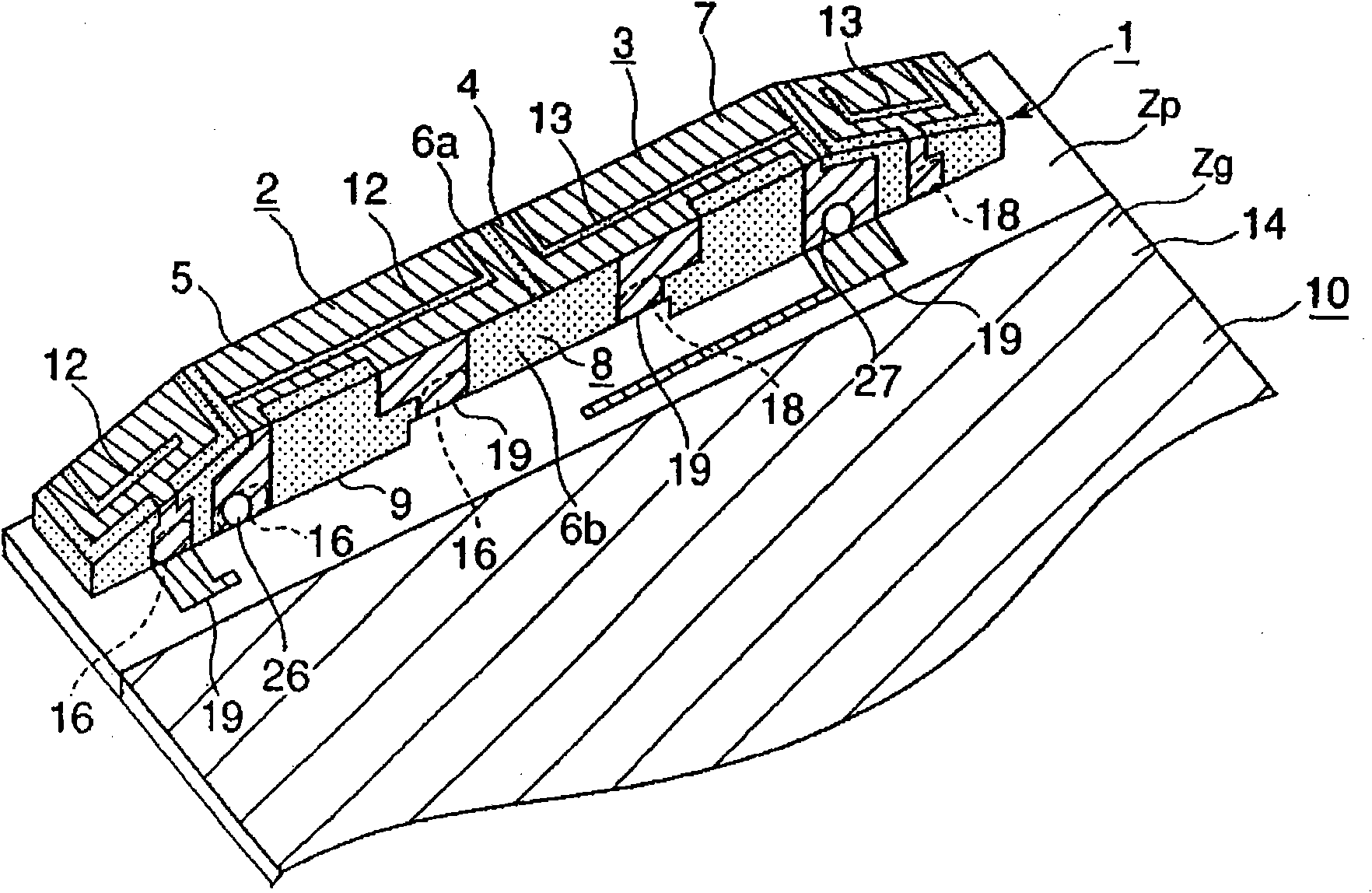
[0045] Figure 1a is a schematic perspective view of the antenna structure of the first embodiment. Figure 1b is from Figure 1a Schematic perspective view of the antenna structure viewed from the rear.

[0046] The antenna structure of the first embodiment includes an antenna element 1 and a substrate 10 . The substrate 10 is a circuit substrate of a wireless communication device such as a mobile phone. This substrate 10 has a ground region Zg where the ground electrode 14 is formed, and a non-ground region Zp where the ground electrode 14 is not formed. In the first embodiment, the non-ground region Zp is formed at one end of the substrate 10 . In addition, a wireless communication circuit (high frequency circuit) is formed on the substrate 10 .

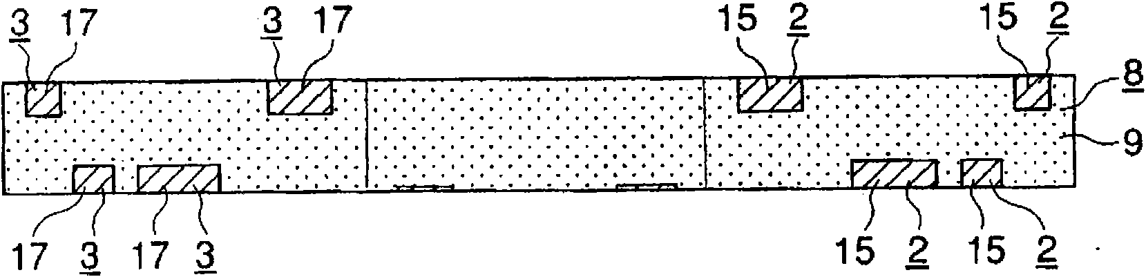
[0047] The antenna element 1 has a dielectric substrate 8 formed of, for example, LCP (Liquid Crystal Polyester Re...


PUM


Abstract

An antenna element (1) is disposed in a non-ground region (Zp) of a substrate (10) having a ground region. The antenna element (1) has a feeding radiation electrode (2) performing an antenna operation and a non-feeding radiation electrode (3), which are formed in a loop shape passing across the upper surface (4) and side surfaces (6a, 6b) of a dielectric base (8) having a substantially rectangular solid shape. The end sides of the loop of the electrodes (2, 3) are formed as respective open ends (5, 7). The antenna element (1) is mounted on the substrate (10) selectively in either an upward mounting mode, in which the open ends (5, 7) are disposed so as to be positioned on the upper surface (4) of the dielectric base (8), or a lateral mounting mode, in which the open ends (5, 7) are disposed so as to be positioned on a side surface by tilting the dielectric base (8) from the upward mounting mode as indicated by an arrow (R). With this mounting mode selection, a region where a voltage at the resonant frequency of the antenna operation becomes maximum is positioned upwardly away from the non-ground region in the upward mounting mode and laterally away from the non-ground region in the lateral mounting mode.

Description

technical field [0001] The present invention relates to an antenna structure provided in a wireless communication device such as a mobile phone, and a wireless communication device having the antenna structure. Background technique [0002] In recent years, antenna structures of various structures have been proposed (for example, refer to Patent Documents 1, 2, and 3). The antenna structures described in Patent Documents 1 to 3 all have a dielectric substrate. For example, in the invention described in Patent Document 2, Figure 7 The shown cuboid-shaped base body 41 is arranged in the antenna structure. A conductor 42 is provided inside the base body 41 . The conductor 42 is wound helically in the longitudinal direction of the base body 41 . In other words, the conductor 42 is wound such that the helical rotation axis direction X extends in the longitudinal direction of the base body 41 . In addition, it is configured such that a voltage can be applied to the conductor ...

Claims


Application Information

Patent Timeline
Patent Type & Authority Applications(China)
IPC IPC(8): H01Q1/38H01Q1/24
CPCH01Q9/26H01Q1/243
Inventor 尾仲健吾石原尚冰见佳弘村山卓也
Owner MURATA MFG CO LTD
Why Eureka
Try Eureka