
Hydraulically-driven self-cleaning laminated filtering device of micro-irrigation system

A laminated filtration and hydraulic drive technology, which is applied in fixed filter element filters, filtration and separation, chemical instruments and methods, etc. Irrigation system, aggravating the investment of micro-irrigation system, etc., to achieve the effect of low maintenance cost, compact space occupation, and small installation footprint

Inactive Publication Date: 2010-12-29
王栋
View PDF0 Cites 12 Cited by
  • Summary
  • Abstract
  • Description
  • Claims
  • Application Information

AI Technical Summary

Problems solved by technology

At present, almost all of the self-cleaning filters used in the world rely on external power sources to complete the automatic backwashing function. Meet the high-tech development requirements of water-saving irrigation, energy saving and consumption reduction
In this regard, filter experts and scholars from all over the world have made various attempts to research and practice, but have not developed a filter that is completely suitable for micro-irrigation systems and does not require any external energy sources such as: wind, water, electricity, gas, batteries, etc. The internal energy of the filter can realize automatic filtration, automatic cleaning and automatic sewage filter

Method used


Image

  • Hydraulically-driven self-cleaning laminated filtering device of micro-irrigation system
  • Hydraulically-driven self-cleaning laminated filtering device of micro-irrigation system

Examples


Embodiment Construction

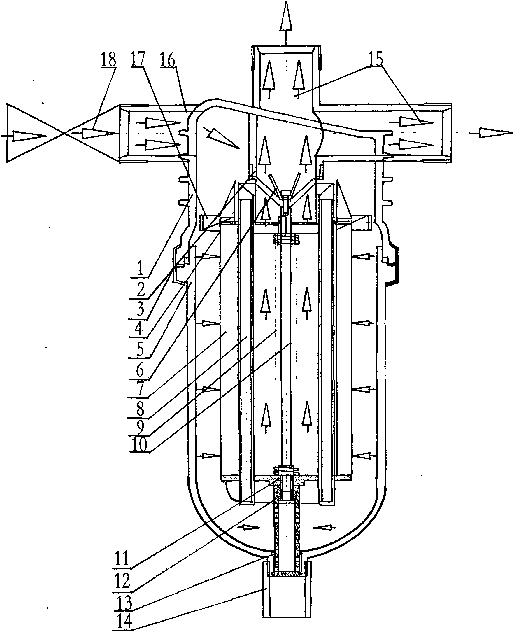
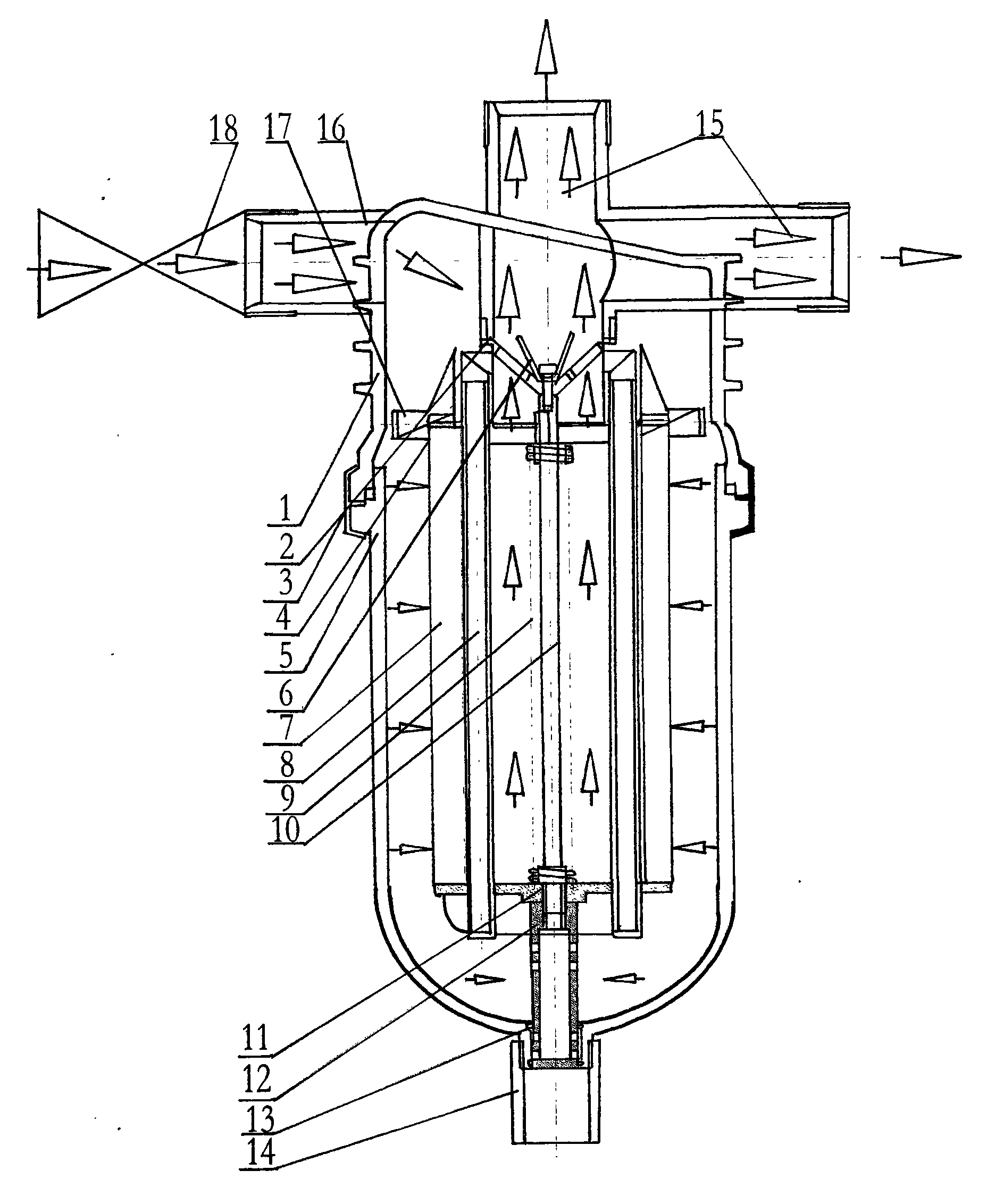
[0009] like figure 1 As shown, the upper shell 1 and the lower shell 5 of the hydraulically driven self-cleaning laminated filter device of the micro-irrigation system are sealed and connected to form a filter cavity through a quick connection clamp 3, and the upper part of the upper shell 1 is provided with a filter cavity. The water inlet 16 and the water outlet 15 communicate with each other, a hydraulic valve 18 is connected to the water inlet 16, a filter lamination group 7 is arranged in the filter cavity, and the filter lamination group 7 is formed with a filter cavity. The filter core cavity is concentric, the filter core cavity is communicated with the water outlet 15, the lower part of the filter lamination group 7 is installed with a lamination connection gland 11, and the inner sleeve of the filter lamination group 7 is connected with a backwashing injector 8, filtering The upper part of the lamination group 7 is provided with a connection seat 3, the upper part of...


PUM


Abstract

The invention discloses a hydraulically-driven self-cleaning laminated filtering device of a micro-irrigation system. The filtering device comprises a filtering cavity consisting of an upper shell and a lower shell, wherein a filtering lamination set is arranged in the filtering cavity; the lower part of the filtering lamination set is provided with a lamination connecting gland; a back wash ejector is sleeved in the filtering lamination set; the upper part of the filtering lamination set is provided with a connecting seat; the upper part of the connecting seat is hermetically connected with a water outlet; the connecting seat is connected with a spiral disk; a back wash piston lever is axially arranged on an axial line of a filter core chamber; the top end of the back wash piston lever is provided with a back wash gasket, while the bottom end is connected with a back wash drainer after passing through the lamination connecting gland; and the back wash drainer is extended out of the bottom of the lower shell and communicated with a back wash drainage connecting pipe. According to the requirement of micro-irrigation on water treatment, a two-stage three-dimensional filtering mode formed by the lamination set and the spiral disk is innovatively designed and invented by researching theoretical basis of design of micro-irrigation filtering equipment; and automatic cleaning and automatic drainage are realized by using centrifugal sedimentation self-cleaning of the spiral disk and energy of water fluid in a filter consisting of a hydraulically-driven piston, a back wash filter core bracket and a drainage device.

Description

technical field [0001] The invention relates to a water quality filtration device for a micro-irrigation system, in particular to a hydraulic-driven self-cleaning laminated filter device for a micro-irrigation system. Background technique [0002] The filter is an indispensable water purification treatment equipment for the micro-irrigation system, which is directly related to the normal operation of the micro-irrigation system and the service life of the system. With the increasing shortage of water resources and energy in the world and the continuous progress of energy-saving technology, based on meeting the requirements of reducing operating costs and lower water head pressure, we are committed to developing automatic cleaning and filtering devices with no external energy consumption and a high degree of automation. The mainstream direction of filter research and development in various countries. At present, the automatic backwashing function of self-cleaning filters use...

Claims


Application Information

Patent Timeline
Patent Type & Authority Applications(China)
IPC IPC(8): B01D29/33B01D29/66
Inventor 王栋
Owner 王栋
Learn More