
Disc-type discharging machine

A discharge machine and disc-type technology, applied in loading/unloading, containers, packaging, etc., can solve the problems of limited storage capacity, large vibration, high motor speed, etc., and achieve the effect of stable and reliable equipment, small vibration and sufficient power

Inactive Publication Date: 2010-12-29
LIYANG YUDA MASCH CO LTD
View PDF0 Cites 11 Cited by
  • Summary
  • Abstract
  • Description
  • Claims
  • Application Information

AI Technical Summary

Problems solved by technology

This discharge method has the following disadvantages: due to the limitation of the size of the feed inlet of the screw conveyor, the storage capacity is limited, and it cannot be made too large, otherwise the material will accumulate at the outlet; at the same time, it is limited by the working mode of the screw conveyor. , material blocking may occur during the conveying process; when the screw conveyor is working, the motor speed is high, there is noise and vibration

Method used


Image

  • Disc-type discharging machine
  • Disc-type discharging machine
  • Disc-type discharging machine

Examples


Embodiment Construction

[0015] The present invention will be further described below in conjunction with accompanying drawing:

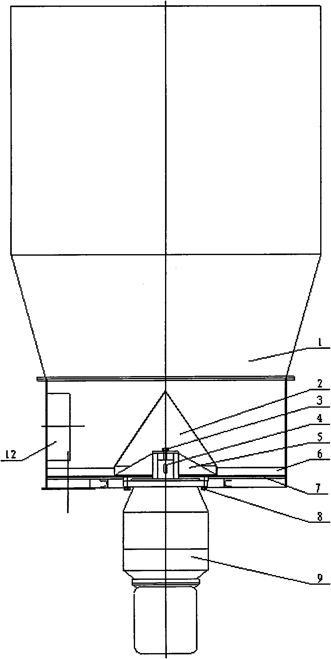
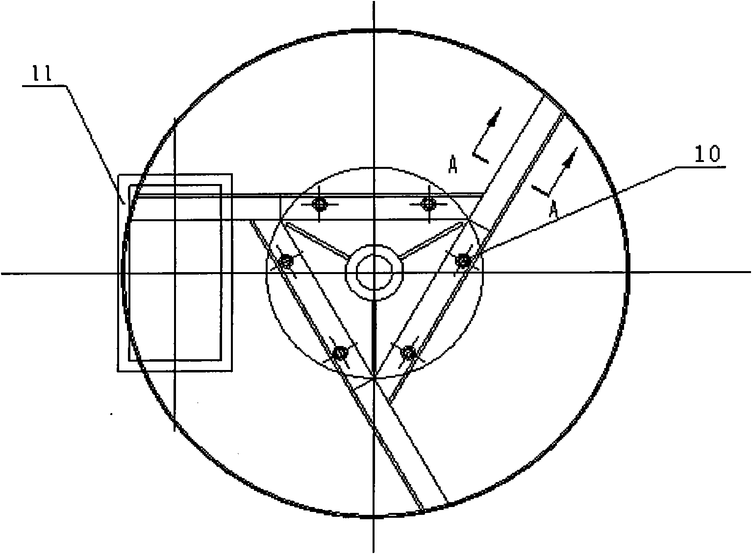
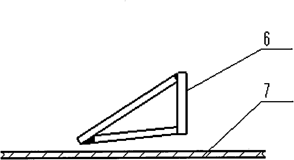
[0016] exist figure 1 , figure 2 , image 3 Among them, the bin body 1 is installed on the bottom plate 7, and the three-handled discharge scraper 6 is fixed on the cutter head 5 through bolts 10. The cone cover 2 is covered on the cutter head 5 and fixed with bolts. The bolt 3 and the key 4 link the cutter head 5 with the gear motor 9, and the gear motor 9 is fixed on the bottom plate 7 by the bolt 8. When the reducer 9 rotates, the cutter head 5 is driven to rotate, and the scraper 6 rotates accordingly to sweep the warehouse , so that the material enters the next process equipment through the discharge port 11.

[0017] The cone cover 2 fixed on the cutter head 5 also rotates accordingly, forcing the material not to accumulate in the middle, which can play the role of guiding the material to the discharge port and reducing the rotation resistance of the cutter head.


PUM


Abstract

The invention discloses a disc-type discharging machine for bilge discharging equipment, which comprises a bin body, a bottom plate, a discharging scraper and a drive device thereof. The bin body is arranged on the bottom plate; the discharging scraper is arranged in the bin body and is driven to rotate by the drive device thereof, and rotating axial direction is vertical; and the bottom of the bin body is provided with a discharge hole which is formed below a plane formed when the discharging scraper is rotated. The disc-type discharging machine has the advantages that: due to no limitation of the size of the discharge hole, the disc-type discharging machine can be used for the large-scale bin capacity and can discharge materials with different specific gravities smoothly, particularly the lightweight material. A conical cover is arranged on a cutter to play a role in guiding the materials to the discharge hole and reducing rotating resistance of the cutter; the disc-type discharging machine avoids material buildup and material blocking due to a scraper stripping mode of the discharge hole, and has the advantages of enough power, small vibration and low noise due to a low speed operating mode; and the equipment is more stable and reliable.

Description

technical field [0001] The invention relates to a device for discharging material at the bottom of a silo, which belongs to the field of conveying machinery, in particular to a disc discharge machine. Background technique [0002] The discharge equipment at the bottom of the existing warehouse mostly uses a ram-type screw conveyor, which is mainly connected by a screw conveyor through the gate and the bottom of the warehouse, and is transported into the corresponding equipment by the screw conveyor. This discharge method has the following disadvantages: due to the limitation of the size of the feed inlet of the screw conveyor, the storage capacity is limited, and it cannot be made too large, otherwise the material will accumulate at the outlet; at the same time, it is limited by the working mode of the screw conveyor. , Material blocking may occur during the conveying process; when the screw conveyor is working, the motor speed is high, there is noise and vibration. Conten...

Claims


Application Information

Patent Timeline
Patent Type & Authority Applications(China)
IPC IPC(8): B65G65/40B65D88/68
Inventor 刘定龙周巍黄青松高强俊
Owner LIYANG YUDA MASCH CO LTD
Learn More