Hydraulic self-adaption air valve correct-timing variable system of diesel engine and control method thereof

一种气门正时、自适应的技术,应用在发动机控制、控制润滑剂的压力、机械设备等方向,能够解决很难进排气门调整、制造成本低等问题,达到成本低、结构简单、零部件少的效果

Active Publication Date: 2010-12-29
TIANJIN UNIV
View PDF7 Cites 13 Cited by
  • Summary
  • Abstract
  • Description
  • Claims
  • Application Information

AI Technical Summary

Problems solved by technology

Since the intake and exhaust camshafts of high-power diesel engines are divided into two types: "top-mounted" and "side-bottom-mounted", the "side-bottom" camshaft makes the engine structure simple and the manufacturing cost low. At present, it is widely used. Usually its The intake and exhaust valves are driven by the same camshaft, so it is difficult to adjust the intake and exhaust valves separately, so the variable valve technology for high-power diesel engines needs to be developed

Method used


Image

  • Hydraulic self-adaption air valve correct-timing variable system of diesel engine and control method thereof
  • Hydraulic self-adaption air valve correct-timing variable system of diesel engine and control method thereof
  • Hydraulic self-adaption air valve correct-timing variable system of diesel engine and control method thereof

Examples


Embodiment Construction

[0043] The present invention will be described in further detail below in conjunction with the accompanying drawings and specific embodiments.

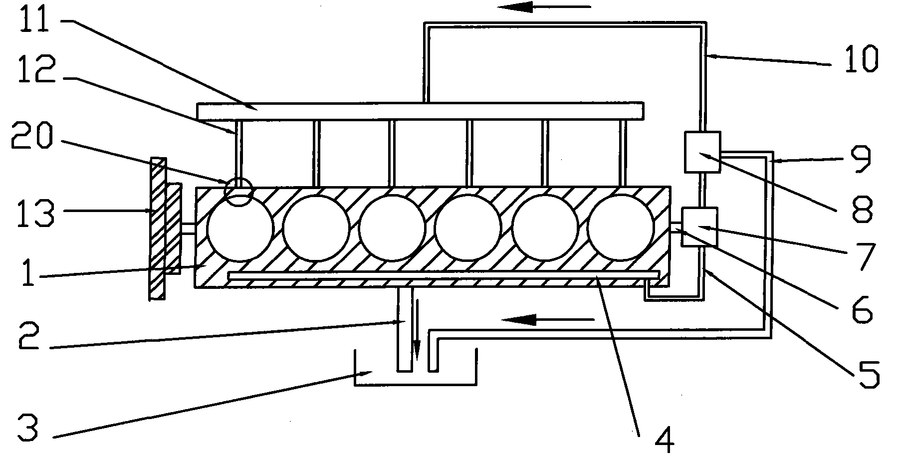
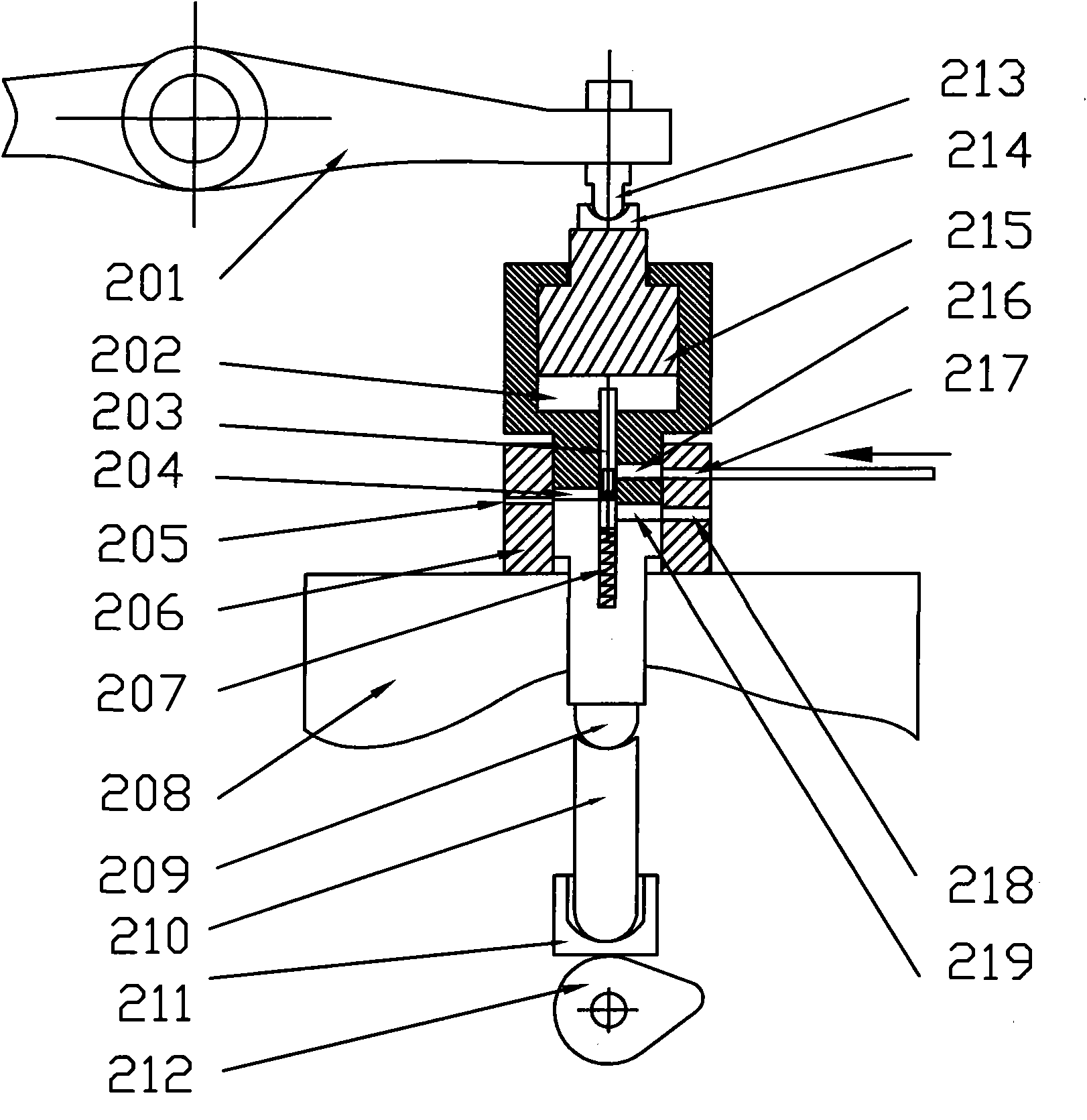
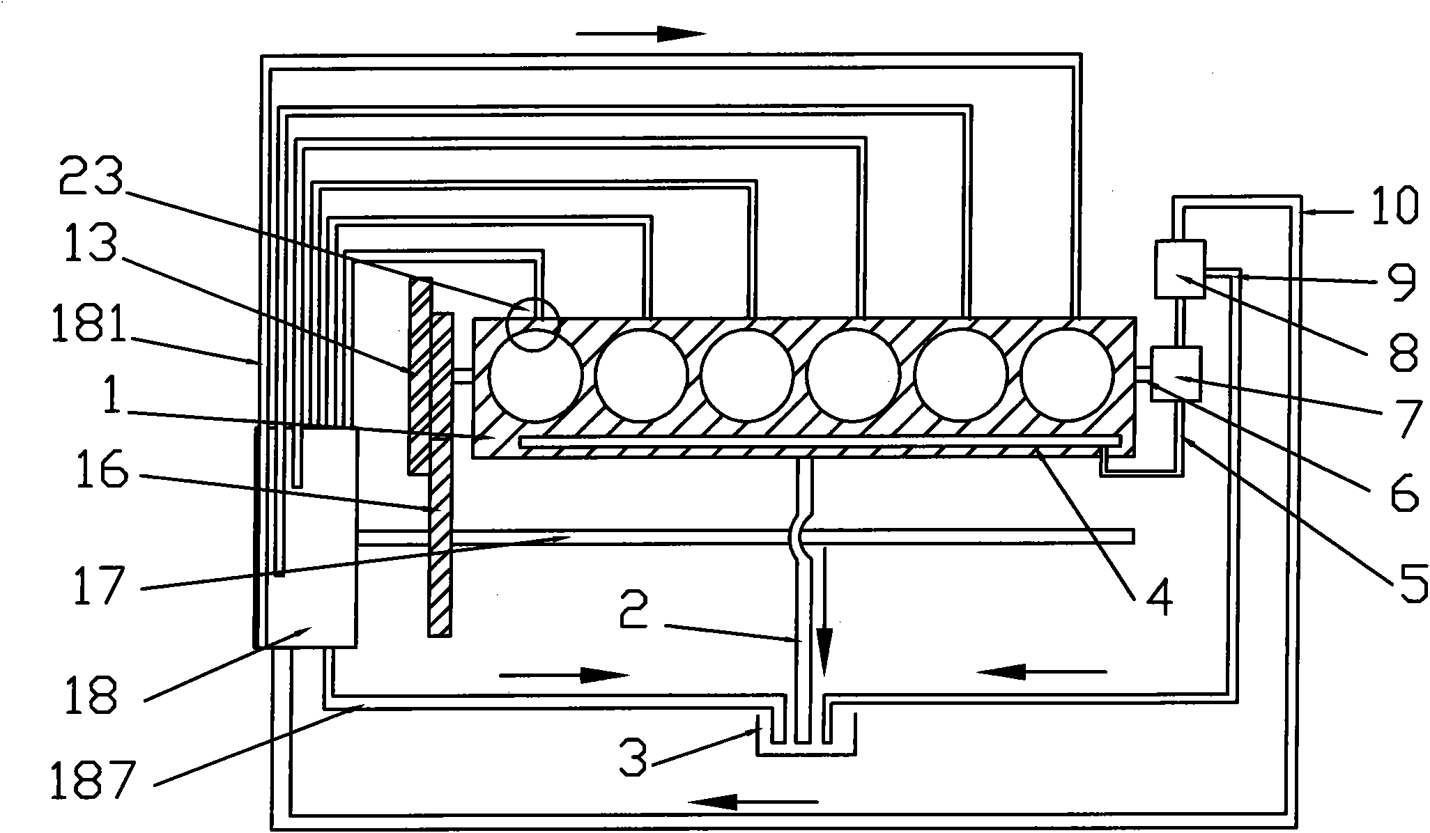
[0044] The purpose of the diesel engine hydraulic self-adaptive valve timing variable system of the present invention is to realize the variable valve timing on the side bottom camshaft diesel engine, mainly by adding a set of self-adaptive push rod length changing mechanism on the original engine push rod , according to the actual needs of the engine, the length of the push rod can be changed by means of the lower push rod in the mechanism, thus forming a combined intake valve push rod.

[0045] The movement of the hydraulic plunger in the adaptive push rod length changing mechanism is realized by pushing the hydraulic plunger (piston) to move up and down through the pressure oil entering and flowing out of the pressure chamber of the adaptive push rod length changing mechanism. The process of hydraulic oil flowing in and out is auto...


PUM


Abstract

The invention discloses a hydraulic self-adaption air valve correct-timing variable system of an internal combustion engine, comprising an oil pump on a power output shaft of an engine, wherein the oil pump is connected with a pressure-adjusting reversing valve, a main lubricating oil channel of the engine is connected with the oil pump through an oil inlet pipe of the oil pump, the pressure-adjusting reversing valve is also connected with an oil delivering pipe and an oil returning pipe, and the oil delivering pipe is connected with a main oil supply pipe; the working medium of the system is engine oil; the oil inlet pie of the oil pump gets oil from the main lubricating oil channel of the engine; the oil pump is connected with the power output shaft of the engine; the pressure-adjusting reversing valve adjusts the pressurized pressure oil of the oil pump to the proper working pressure and switches the flow direction of the pressure oil, thereby accomplishing the switch of the working mode of the system; and the main oil supply pipe, the oil delivering pipe and each working cylinder of the engine are connected through a self-adaption push rod length charging mechanism. Meanwhile, the invention also discloses a control method of the system. The hydraulic self-adaption air valve correct-timing variable system is divided into a working mode and a non-working mode as required, can meet the actual demand of the engine and also take the effects of energy saving and environmental protection.

Description

technical field [0001] The invention relates to a hydraulic self-adaptive valve timing variable system and control method of an internal combustion engine. Background technique [0002] Traditional piston four-stroke engines generally use a mechanical camshaft to drive the valve train of the intake and exhaust valves. The movement of the valves is controlled by the mechanical transmission between the crankshaft and the camshaft, and between the camshaft and each valve. This mechanical mechanism has long proven to be simple, effective, reliable, and relatively inexpensive. However, the parameters such as the opening time and phase of the valve train are fixed and cannot be adjusted during engine operation, and the timing cannot be changed under different operating conditions, so the engine performance potential cannot be fully utilized. The combustion process of modern advanced internal combustion engines needs to adjust the opening and closing timing and lift of the valve....

Claims


Application Information

Patent Timeline
Patent Type & Authority Applications(China)
IPC IPC(8): F01L1/34F01L9/02F01M1/02F01L1/18F02D13/02F01L9/14F01L9/40
CPCF02B3/06F01L1/34F01L2001/34423Y02T10/18F01L1/181F01L2013/0089F01L1/146F01L9/025F02D13/0226F01L13/0031Y02T10/12F01L9/14F01L9/10F01L1/18F01M1/02F02D13/02F02B67/06F01L1/14F02D11/06F01M1/16
Inventor 苏万华战强裴毅强刘二喜吴松林
Owner TIANJIN UNIV
Why Eureka
Try Eureka