Hydraulic oil tank cooling device

A technology of cooling device and hydraulic oil tank, which is applied in the direction of fluid pressure actuating device, fluid pressure actuating system components, mechanical equipment, etc. Hydraulic pump set installation and other issues, to achieve the effect of convenient maintenance and connection of cooling water pipes, improved heat exchange effect, and simple structure

Inactive Publication Date: 2010-12-29
WUXI DONGZHOU MARINE FITTINGS
View PDF6 Cites 3 Cited by
  • Summary
  • Abstract
  • Description
  • Claims
  • Application Information

AI Technical Summary

Problems solved by technology

However, since the steering gear rarely works at a large angle continuously for a long time during operation, it shows that the general utilization rate of this cooler device is low, which increases the production cost of the factory; since the cooler is installed outside the fuel tank, it is extra large The external dimensions of the hydraulic pump set are not conducive to the installation of the hydraulic pump set in the steering gear cabin

Method used


Image

  • Hydraulic oil tank cooling device
  • Hydraulic oil tank cooling device

Examples


Embodiment Construction

[0015] The present invention will be further described below in conjunction with specific drawings and embodiments.

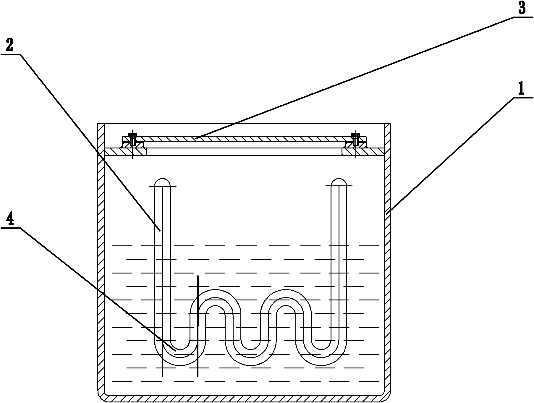
[0016] As shown in the figure: the hydraulic oil tank cooling device includes a fuel tank body 1, a cooling pipe 2, a repair cover 3, a U-shaped unit 4, and the like.

[0017] The present invention includes a fuel tank body 1, in which a cooling pipe 2 is arranged, and the cooling pipe 2 is connected to the inner wall of the fuel tank body 1 through threads; the cooling pipe 2 is composed of several U-shaped units 4;

[0018] Both ends of the cooling pipe 2 are respectively provided with a water inlet and a water outlet;

[0019] Install repair cover 3 by screw on the upper end of fuel tank case body 1.

[0020] The cooling device of the present invention can perform cooling inside the oil tank when the utilization rate of the oil tank is low. The cooling pipe 2 is connected with the fuel tank body 1 through threads, so that the cooling pipe 2 can be disassem...


PUM


Abstract

The invention relates to a hydraulic oil tank cooling device comprising an oil tank body. The hydraulic oil tank cooling device is characterized in that a cooling pipe is arranged in the oil tank body; the cooling pipe is connected with the inner wall of the oil tank body by threads and is composed of a plurality of U-shaped units; the two ends of the cooling pipe are respectively provided with a water inlet and a water outlet; and the upper end of the oil tank body is provided with a repairing cover by bolts. The invention has the following advantages and effects: the hydraulic oil tank cooling device of the invention can prevent water leaked from oil pipe joint from entering the oil tank and is convenient to maintain and connect the cooling water pipe; 2. the cooling pipe and liquid oil have big contact surface so as to improve the heat exchange effect; 3. the cooling pipe is arranged in the oil tank, which brings compact and beautiful structure; and 4. compared with a water-cooling oil cooler, the pipe-type cooling pipe has simple structure and low production cost.

Description

technical field [0001] The invention relates to a hydraulic oil tank cooling device, in particular to a hydraulic oil tank cooling device for a hydraulic steering gear. Background technique [0002] When the ship is sailing in the summer navigation area, if the hydraulic steering gear works at a large angle for a long time, the oil temperature in the fuel tank will rise rapidly, which may exceed the working temperature required by the steering gear system, causing damage to the hydraulic components. Affected the work of the steering gear. This requires that the oil in the fuel tank must be cooled down. The two most commonly used cooling methods today are air cooling and water cooling, among which water cooling is widely used as water-cooled oil cooler. This cooler is installed on the outside of the tank and is the best cooling device. However, since the steering gear rarely works at a large angle continuously for a long time during operation, it shows that the general ut...

Claims


Application Information

Patent Timeline
Patent Type & Authority Applications(China)
IPC IPC(8): F15B21/04
Inventor 宋勇荣华建春
Owner WUXI DONGZHOU MARINE FITTINGS
Why Eureka
Try Eureka