
Opposite plug type pliers

A technology of opposing pistons and caliper bodies, applied in the direction of brake actuators, gear transmission mechanisms, axial brakes, etc., can solve the problems of low cutting efficiency, difficulty in direct use, poor assembly of pistons, etc., and achieve manufacturing Efficiency improvement, suppression of liquid leakage, and reduction in the number of parts

Inactive Publication Date: 2010-12-29
HONDA MOTOR CO LTD
View PDF5 Cites 11 Cited by
  • Summary
  • Abstract
  • Description
  • Claims
  • Application Information

AI Technical Summary

Problems solved by technology

[0006] In the prior art described in the above-mentioned Patent Document 1, the two-part caliper bodies are connected by bolts, and the number of parts is large.
In addition, in the assembly process of the caliper body, for example, after the two caliper bodies are fixed with bolts, a total of four pistons need to be arranged in the cylinder bore from the gap for disposing the brake pads, wherein the cylinder bore is in the Formed on the action part, the assembly of the piston is poor
Moreover, when cutting the cylinder bore for inserting the piston on each caliper body, since the caliper body is divided into two parts, it is difficult to directly use a common floating cutting device or a fixture, etc., and the working efficiency of the cutting process is also low. Low

Method used


Image

  • Opposite plug type pliers
  • Opposite plug type pliers
  • Opposite plug type pliers

Examples


Embodiment Construction

[0030] Hereinafter, preferred embodiments of the opposed-piston caliper according to the present invention will be described based on the relationship between the opposed-piston caliper and a brake caliper to which the opposed-piston caliper is applied, with reference to the accompanying drawings. Describe in detail.

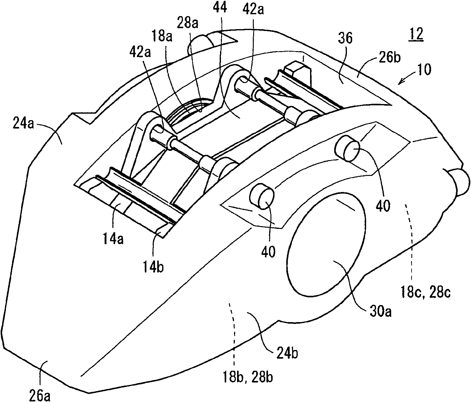
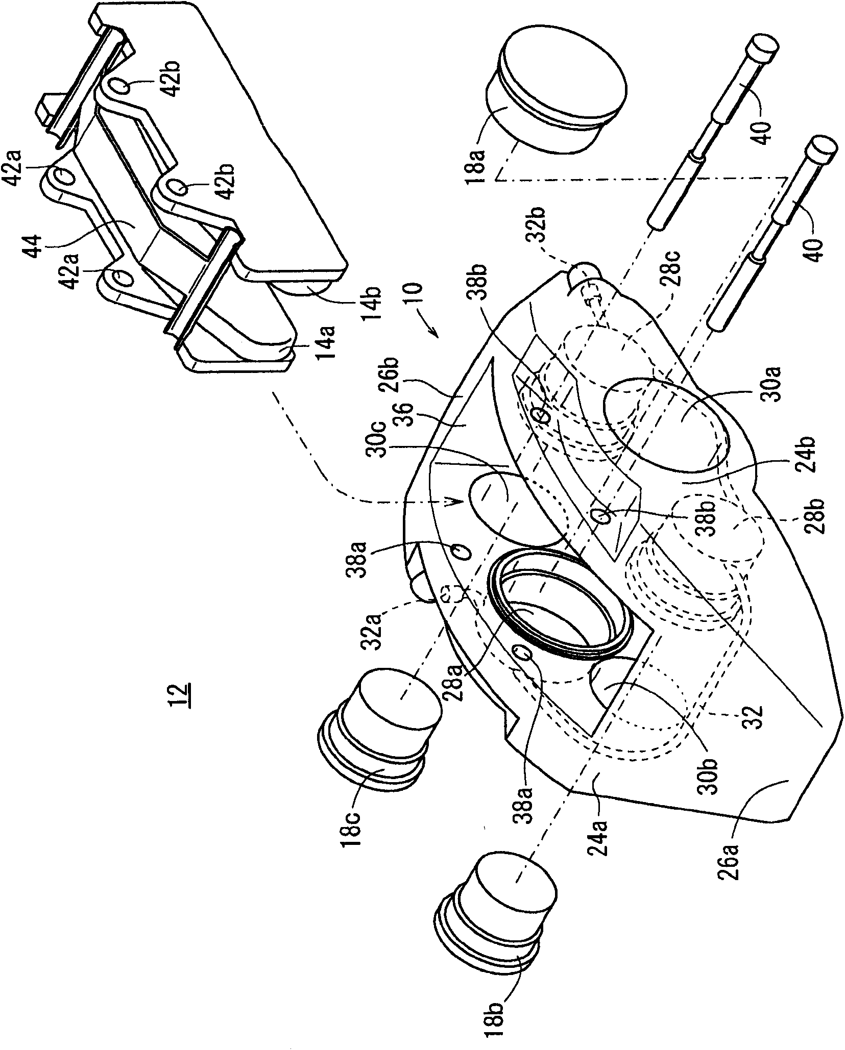
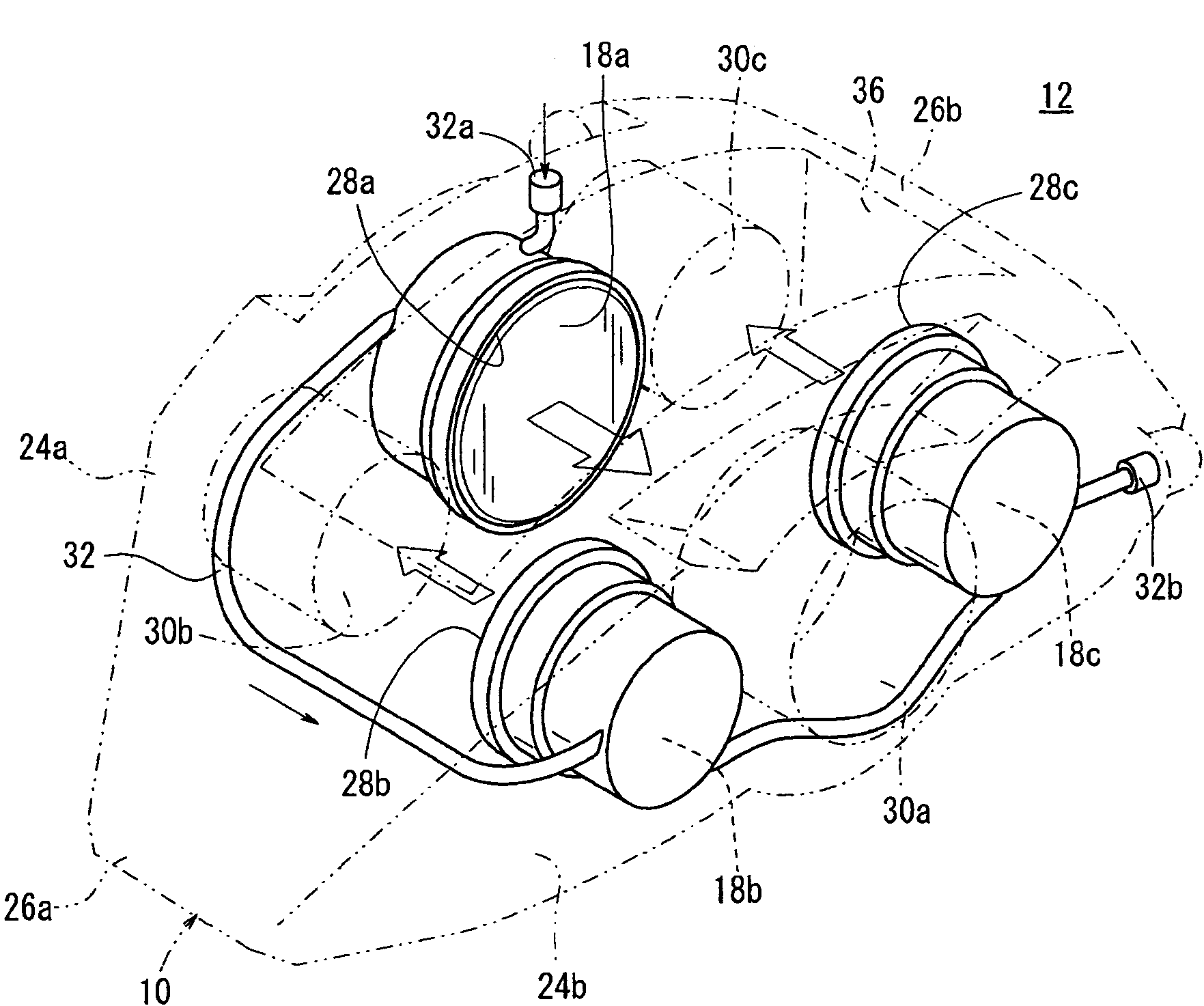
[0031] figure 1 It is a perspective view of a brake caliper 12 to which an opposed-piston caliper body 10 according to an embodiment of the present invention is applied, figure 2 yes figure 1 An exploded perspective view of the brake caliper 12 is shown. in addition, image 3 yes means figure 1 A perspective view of the hydraulic system of the brake caliper 12 is shown.

[0032] Such as figure 1 with figure 2 As shown, the brake caliper 12 is a brake mechanism for clamping a disc rotor that rotates together with a wheel of a motor vehicle, etc. ”); a pair of brake blocks 14a, 14b configured in the caliper body 10; Figure 5 ) a plurality of (three in ...


PUM


Abstract

The invention provides opposite plug type pliers (10) capable of reducing element number and improving production efficiency, comprising a pair of acting parts (24a, 24b) arranged at two sides of a disc rotor (16), a bridge part (26a, 26b) connecting the two acting parts (24a, 24b), and more than one cylinder hole (28a-28c) for inserting plugs (18a-18c), which are respectively formed at the two acting parts (24a, 24b). The cylinder holes (28a-28c) are formed in an axially misaligned manner at the two acting parts (24a, 24b). Cylinder holes (28a-28c) at the side of one acting part (24a, 24b) are opposite to through holes (30a,-30c) at the other acting part (24b, 24a).

Description

technical field [0001] The present invention relates to an opposed-piston caliper body in which cylinder holes for piston insertion are respectively formed on a pair of action parts disposed on both sides of a disc rotor. Background technique [0002] Vehicles such as four-wheeled motor vehicles are equipped with a disc brake device having a brake caliper that is pressed by a piston provided on the caliper body and clamped by brake pads to rotate integrally with the wheel. The mechanism of the disc rotor. Generally, a brake caliper is constituted by a mechanism configured to clamp a disk rotor through a pair of acting portions connected by a bridge portion, and to press a brake pad through a hydraulically driven piston provided at the acting portions. [0003] As such a brake caliper, a floating type (collet type) caliper is generally used in which a piston is arranged only on one side of the action part, and the reaction force generated by driving the piston draws the othe...

Claims


Application Information

Patent Timeline
Patent Type & Authority Applications(China)
IPC IPC(8): F16D65/02F16D55/22F16D65/18
CPCF16D55/228F16D2055/0016F16D2121/02F16D2250/0015F16D2055/0091
Inventor 林则彦小池明彦川上洋生
Owner HONDA MOTOR CO LTD
Learn More