Lighting device

A technology for lighting devices and heat dissipation devices, which is applied to lighting devices, lighting device components, and lighting device cooling/heating devices, etc., can solve the problems of low heat dissipation efficiency, slow hot air dissipation, waste, etc. sexual effect

Inactive Publication Date: 2010-12-29
FOXSEMICON INTEGRATED TECHNOLOGY (SHANGHAI) INC +1
View PDF0 Cites 8 Cited by
  • Summary
  • Abstract
  • Description
  • Claims
  • Application Information

AI Technical Summary

Problems solved by technology

At present, the usual practice in the industry is to attach heat dissipation fins under the light source LEDs of the lighting device to dissipate heat. In the way of convection, the hot air in the heat dissipation fins dissipates slowly, and the hot air tends to accumulate around the LEDs, resulting in low heat dissipation efficiency
If the external electric fan provides forced convection, and the fan is usually installed in the heat dissipation module or lighting device, this will make the fan difficult to disassemble and clean
When the fan is not working, the LEDs are prone to overheating, which greatly reduces the life of the LEDs, and may result in the need to disassemble the entire lighting device, resulting in waste or inconvenience

Method used


Image

  • Lighting device
  • Lighting device
  • Lighting device

Examples


Embodiment Construction

[0013] The embodiments of the present invention will be further described in detail below in conjunction with the accompanying drawings.

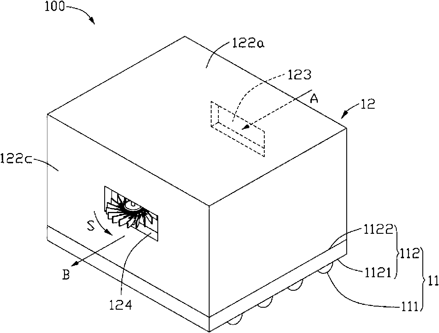
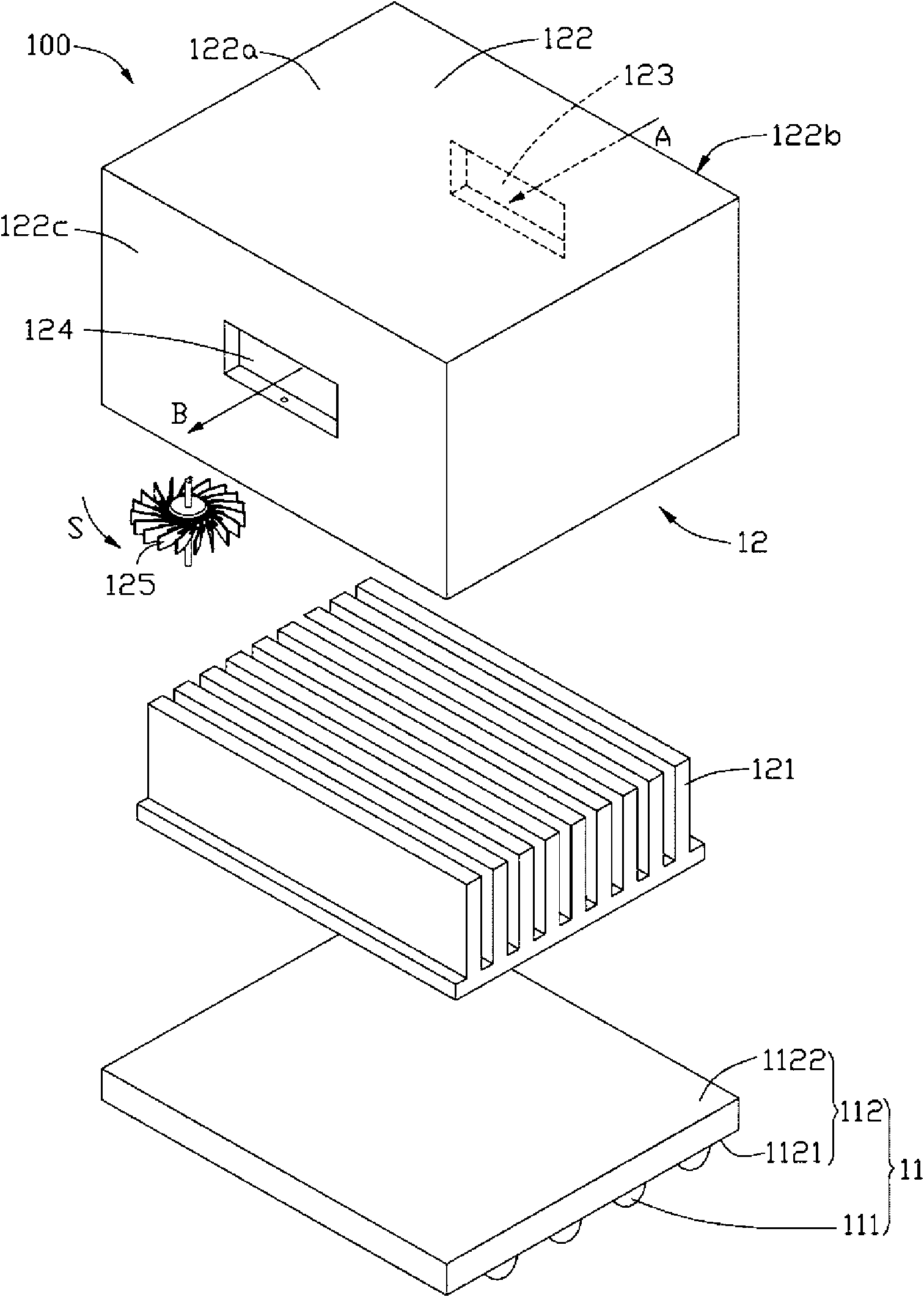
[0014] see figure 1 and figure 2 , the lighting device 100 provided by the first embodiment of the present invention includes a light source 11 and a heat dissipation device 12 .

[0015] The light source 11 includes at least one LED 111 and a substrate 112 . The substrate 112 includes a first surface 1121 and a second surface 1122 opposite to the first surface 1121 . The at least one LED 111 is disposed on the first surface 1121 of the substrate 112 and is electrically connected to the substrate 112 .

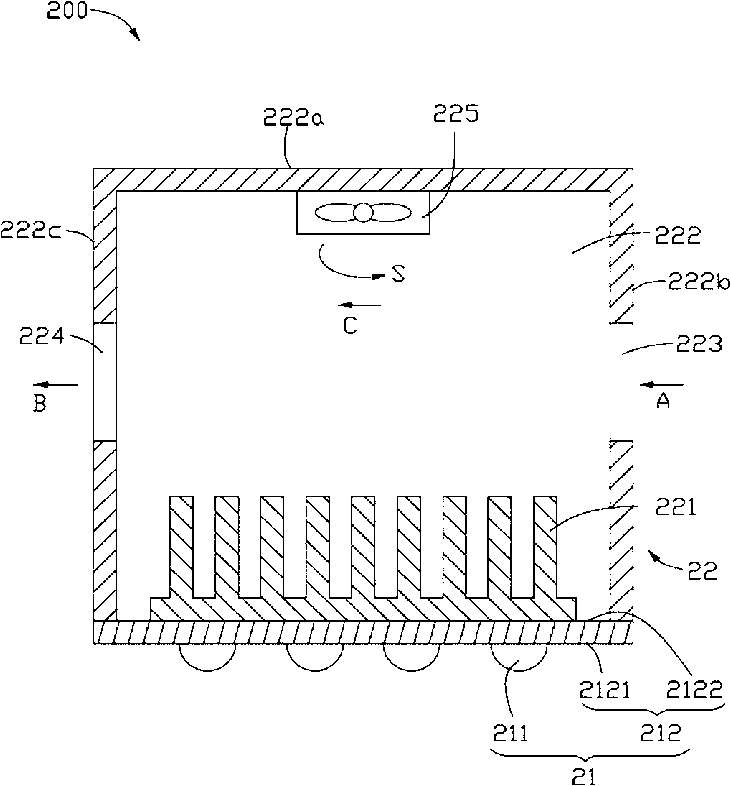
[0016] The heat sink 12 is disposed on the second surface 1122 of the substrate 112 and is thermally connected to the substrate 112 . The heat dissipation device 12 includes a plurality of heat dissipation fins 121 , a hollow shell 122 and a fan 125 .

[0017] The plurality of cooling fins 121 are located in the hollow shell 122 and a...


PUM


Abstract

The lighting device comprises a light source and a radiation device. The light source comprises a substrate and at least one light emitting diode arranged on the substrate. The radiation device comprises a fan for cooling the light source, a hollow shell, an air inlet and an air outlet, wherein the air inlet and the air outlet are arranged on the shell; the fan can be arranged on the hollow shell detachably; and the direction of an active air flow generated by the fan is positioned above a plane on which the fan rotates. When the fan works, the air flow generated accelerates the flowing of the air in the hollow shell, carries away heat generated by the light source and flows out from the air outlet; after the air flows out from the air outlet quickly, the air pressure in the shell is reduced, so that external cold air flows in from the air inlet quickly; and thus, the air in and out of the hollow shell flows quickly, and the radiation efficiency is improved.

Description

technical field [0001] The invention relates to a lighting device, in particular to a light-emitting diode lighting device with good heat dissipation efficiency. Background technique [0002] Light Emitting Diode (LED, Light Emitting Diode) has the advantages of high brightness, low operating voltage, low power consumption, easy matching with integrated circuits, simple driving, and long life, so it can be used as a light source and widely used in the lighting field. For details, please refer to Joseph Bielecki et al. wrote Thermal Considerations for LED Components in an Automotive Lamp in the 2007 IEEE, 23rd IEEE SEMI-THERM Symposium. [0003] When the light-emitting diode emits light, its own temperature will gradually increase. When the temperature reaches a certain level, such as greater than 120 degrees Celsius, its operating voltage, light-emitting wavelength, and light output intensity will be greatly affected. At present, the usual practice in the industry is to att...

Claims


Application Information

Patent Timeline
Patent Type & Authority Applications(China)
IPC IPC(8): F21S2/00F21V19/00F21V29/00F21V29/02H01L23/367H01L23/467F21Y101/02
CPCF21Y2105/001F21K9/00F21V29/02F21Y2101/02F21S2/005F21V29/677F21V29/763F21Y2105/10F21Y2115/10
Inventor 赖志铭刘育彬
Owner FOXSEMICON INTEGRATED TECHNOLOGY (SHANGHAI) INC
Why Eureka
Try Eureka