Efficient permanent magnet coupling device for transmission shaft

A technology of permanent magnetic coupling and drive shaft, applied in permanent magnetic clutches/brakes, electromechanical devices, electric brakes/clutches, etc., can solve problems such as disorder, inconsistency, and increased conductor resistivity

Inactive Publication Date: 2010-12-29
林贵生
View PDF1 Cites 59 Cited by
  • Summary
  • Abstract
  • Description
  • Claims
  • Application Information

AI Technical Summary

Problems solved by technology

[0011] The inventors have found that the following problems exist in the above-mentioned permanent magnet coupling torque transmission or driving mechanism: the induced eddy currents generated on the conductor rotor disk have no set flow direction and the disorder of the microscopic metal structure inside the conductor disk, they must be It is disordered, inconsistent and boundless, and the same is true of the fact; similarly, because the magnetic field generated by the induced eddy current has no set flux path, there will be some adjacent and opposite or opposite directions in the magnetic coupling process. The induced magnetic fields generated by the messy induced eddy currents cancel each other out, and because there is no set magnetic flux path, the density of the induced magnetic flux is dispersed, causing a large amount of induced electric energy and magnetic energy to be dissipated on the conductor disk or not fully utilized, making the conductor The rotor disk heats up and leads to a series of more serious consequences, such as: temperature rise, conductor resistivity increases, induced eddy current decreases, magnetic torque also decreases, magnetic torque transmission or driving efficiency is not high; temperature rises, permanent The demagnetization effect of the magnet will also be accelerated, resulting in a reduction in the working life of the permanent magnet coupling and the governor. Recently, more advanced heat dissipation measures have to be taken to dissipate heat. It is more difficult to further increase the power of the magnetic coupler, and the product cost is at the top of the list. high

Method used


Image

  • Efficient permanent magnet coupling device for transmission shaft
  • Efficient permanent magnet coupling device for transmission shaft
  • Efficient permanent magnet coupling device for transmission shaft

Examples


Embodiment 1

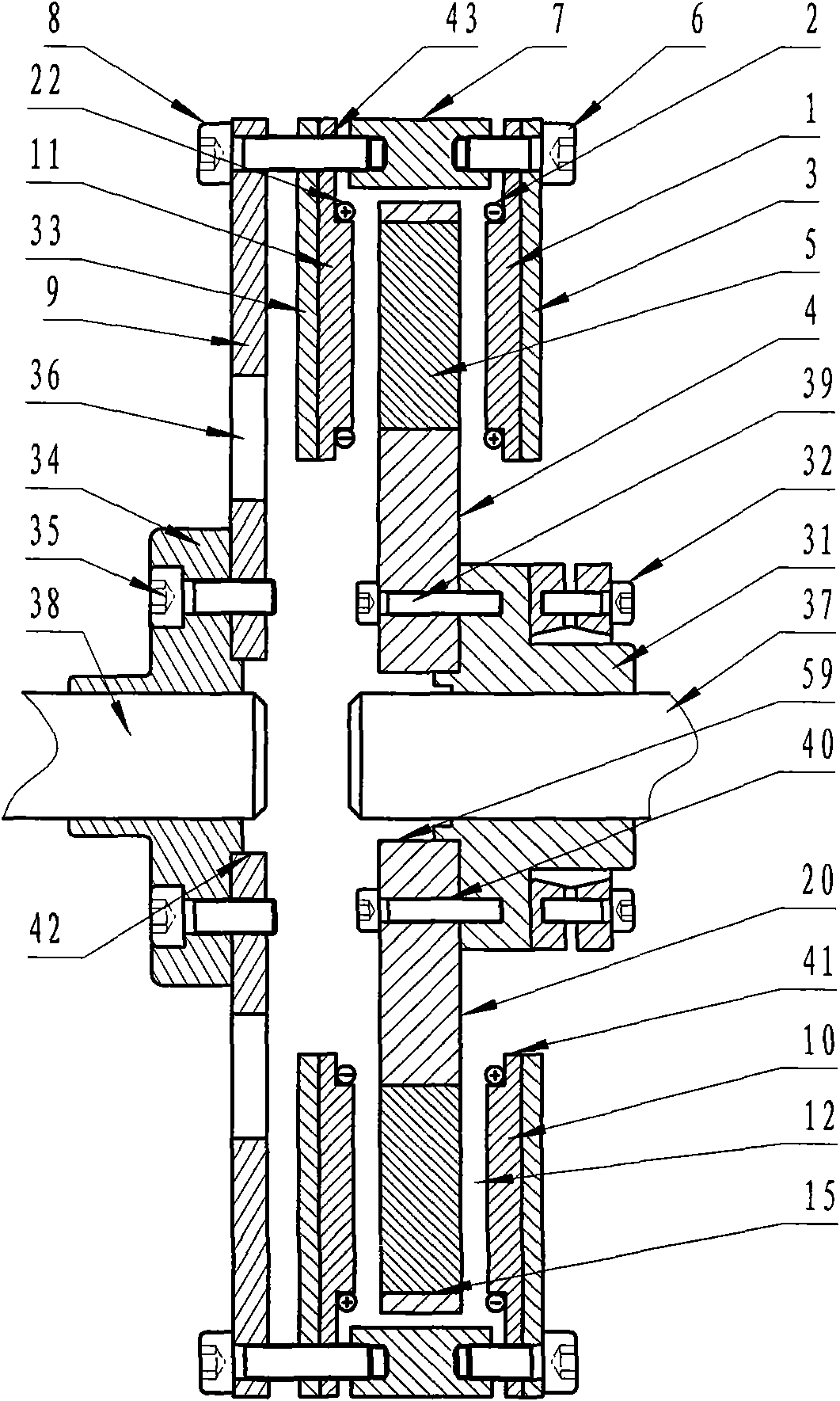
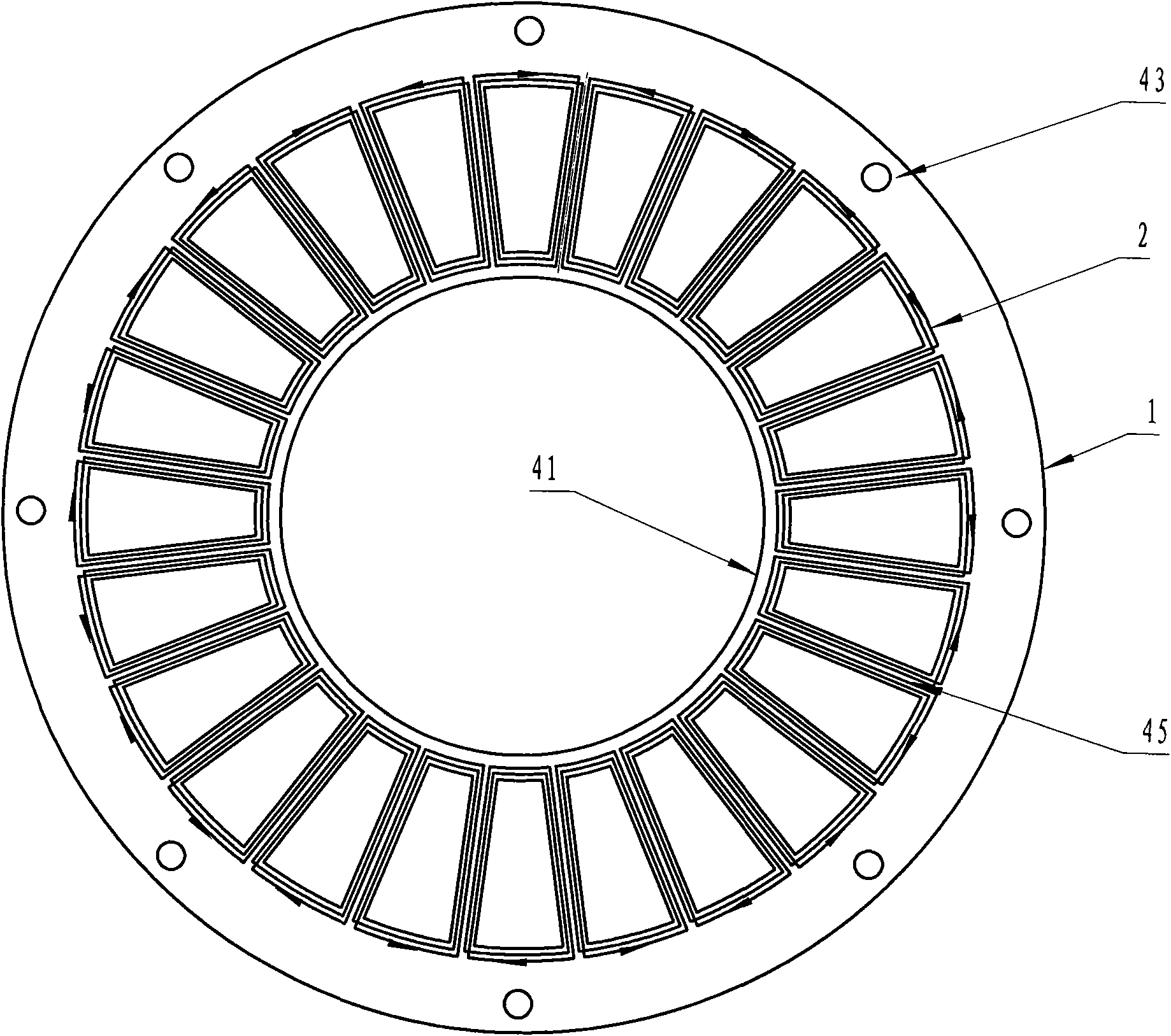
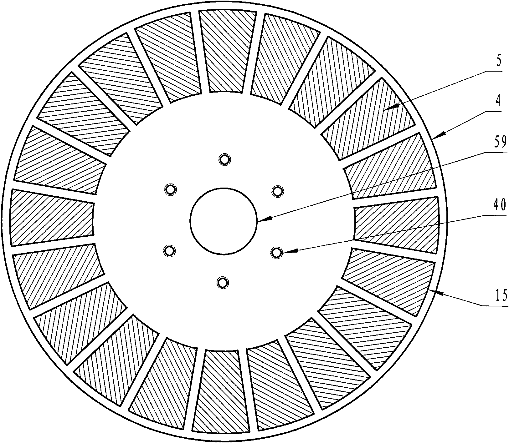
[0056] like figure 1 , figure 2 and image 3 One embodiment of the invention is shown, with two sets of permanent magnetic coupling assemblies arranged "back to back", which consist of two secondary armature winding rotor discs (1 and 2, 11 and 22) and corresponding armature Winding disk coupling mechanism (6, 7, 43, 8 and 9), two adjacent permanent magnet rotor disks are arranged "back to back" and merged into permanent magnet rotor disks (4 and 5) coupled on both sides and matched with them The permanent disk coupling mechanism (39, 40) and the corresponding input coupling (34, 35) and output coupling (31, 32) are composed of the armature winding rotor disk consisting of 24 armature windings (2) and It is composed of an armature winding mounting plate (1) for assembling the armature winding, and the armature winding is a fan-shaped multi-turn armature winding, figure 2 Each armature winding (2) has three turns, the head end and the end short circuit are closed, and the ...

Embodiment 2

[0060] like Figure 4 , Figure 5 and Image 6 As shown, this example is provided with two sets of permanent magnetic coupling components, which are arranged back to back according to "armature winding rotor disc-permanent magnet rotor disc, permanent magnet rotor disc---armature winding rotor disc", using the central short axis and Torque transmission sliding bar structure, which consists of two armature winding rotor disks (101 and 102, 111 and 122) and the corresponding armature winding disk coupling mechanism (106, 107, 143, 108 and 109), two Auxiliary permanent magnet rotor disks (104 and 105) and their matching permanent disk coupling mechanisms (149, 147, 148, 150, 151 and 152) and corresponding input couplings (134, 135) and output couplings (153, 132), the armature winding rotor disc is composed of 24 armature windings (102) and the armature winding mounting plate (101) for assembling the armature winding, and the armature winding is a fan-shaped turn and the turns ...

Embodiment 3

[0063] like Figure 7 , Figure 8 , Figure 9 and Figure 10 As shown, there are four sets of permanent magnetic coupling components in this example, according to "armature winding rotor disk---permanent magnet rotor disk, permanent magnet rotor disk---armature winding rotor disk, armature winding rotor disk--- The permanent magnet rotor disk, the permanent magnet rotor disk --- the armature winding rotor disk" are arranged back to back, and adopt the central short axis and the torque transmission slider structure. There are four differences from Embodiment 2: one is the device Doubled permanent magnetic coupling assembly is added in the middle; the second central turntable (218) is added, and the second center turntable (218) is fixed to the appropriate position on the central short shaft with a keyway, a spline or a tight fit, In order to support the torque transmission slide bar (247) and transmit torque; the third is that the two armature winding mounting plates (260) i...


PUM


Abstract

An efficient permanent magnet coupling device for a transmission shaft comprises armature winding rotor disks and adaptive armature winding disk shaft coupling mechanisms, permanent magnet rotor disks and adaptive permanent magnet disk shaft coupling mechanisms and input and output shaft couplings, wherein the armature winding rotor disks comprise armature windings and armature winding installing disks; the permanent magnet rotor disks comprise a group of permanent magnets and a permanent magnet installing disk; the permanent magnets are respectively assembled on the circumference of the permanent magnet installing disk, with N and S poles staggered; the armature winding rotor disks and the permanent magnet rotor disks are, face to face, coaxially installed and are coupled with the corresponding input and output shaft couplings by the adaptive disk shaft coupling mechanisms; and air gaps exist between the armature winding rotor disks and the permanent magnet rotor disks. The device has the characteristics of higher transmission efficiency, simple and reliable structure, convenient installation, resistance to severe environment, tolerance for shaft eccentricity, load isolation, reduction of vibration and noises, prolonging of equipment life, etc, and has the advantages of not damaging the motors and not affecting the safety of power grids.

Description

technical field [0001] The invention relates to the field of motor drive and load speed regulation systems, in particular to an efficient transmission shaft permanent magnetic coupling device. Background technique [0002] At present, energy saving and consumption reduction has become the focus of the whole society and the goal of scientific development. The electricity consumption of the motor system accounts for about 60% of the global electricity consumption, of which the electricity consumption of fans, pumps, compressors and air-conditioning refrigerators account for 10.4%, 20.9%, 9.4% and 6% of the global electricity consumption respectively. The motor system has a large quantity and a wide range, and the potential for power saving is huge. From a domestic point of view, the total installed capacity of various existing motor systems is about 420 million kilowatts, and the operating efficiency is 10-20 percentage points lower than the advanced level abroad, which is eq...

Claims


Application Information

Patent Timeline
Patent Type & Authority Applications(China)
IPC IPC(8): H02K49/10
CPCH02K49/108
Inventor 林贵生余亚莉
Owner 林贵生
Why Eureka
Try Eureka