Assembling device for display

A technology for display devices and assembling devices, which can be applied to identification devices, nonlinear optics, instruments, etc., can solve the problems of large-scale devices, decreased positioning accuracy, and reduced moving acceleration, and achieves high-precision assembly processing, improved positioning accuracy, and improved positioning accuracy. The effect of reducing inertial mass

Inactive Publication Date: 2012-06-06
SHARP KK
View PDF2 Cites 0 Cited by
  • Summary
  • Abstract
  • Description
  • Claims
  • Application Information

AI Technical Summary

Problems solved by technology

In addition, in the prior art disclosed in Japanese Patent Laid-Open No. 8-85089, a two-axis device that stacks the X-axis linear guide and the Y-axis linear guide is required, and the floating device for holding the member in either technique is difficult. It is very complicated and the device is large
In addition, the above situation will increase the inertial mass and reduce the positioning accuracy when the conveyor is placed. Therefore, it is necessary to increase the size of the tapered shape to absorb positioning errors, and it is difficult to apply it to the side wall of the B / L unit. narrow parts
[0015] In addition, in order to ensure the positioning accuracy on the side of the transfer machine, even if the floating device in the prior art is applied to the parts to be assembled instead of the parts for assembly, although the positioning accuracy on the side of the transfer machine can be improved, the inertial mass of the parts to be assembled Increase, the movement acceleration of the parts that avoid interference during assembly decreases

Method used


Image

  • Assembling device for display
  • Assembling device for display
  • Assembling device for display

Examples


Embodiment Construction

[0069] The preferred embodiments of the present invention will be described in detail below with reference to the accompanying drawings.

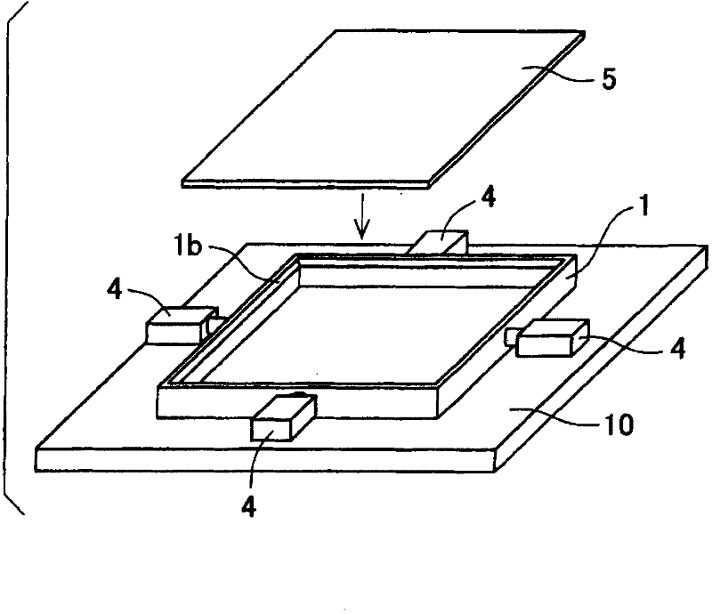
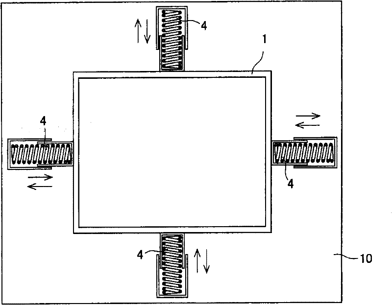
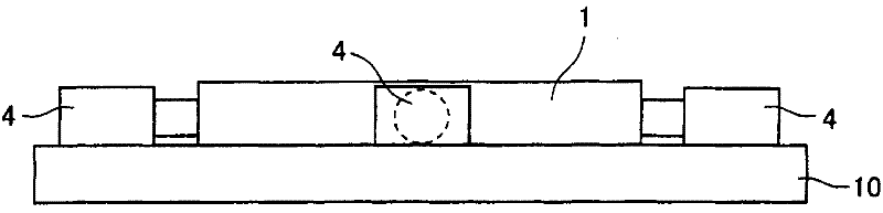
[0070] Embodiments of an apparatus for manufacturing a display device according to the present invention will be described below. figure 1 It is a perspective view illustrating an assembly device according to an embodiment of the present invention, showing a state in which a backlight unit (hereinafter referred to as a B / L unit) 1 and a panel 5 are assembled. In this embodiment, the panel 5 corresponding to the component for assembly is positioned by the suction hand of the transfer machine (not shown), sucked and held, and moved to the component corresponding to the component to be assembled placed on the loading table 10. Assembly is performed directly above the B / L unit 1. In this embodiment, if Figure 2A top view of and Figure 2B As shown in the side view of , the components are held while being centered by pressing the side of th...


PUM


Abstract

Disclosed is an assembling device of a simple structure for assembling, for example, a liquid crystal panel and a backlight unit. In order to attain assembling work with a high accuracy and quickly, the backlight unit (1) is pressed by compression springs (4) for positioning and holding the panel (5), and in such a state, the panel (5) is fitted into the recess of the backlight unit (1) and fixed.

Description

technical field [0001] The present invention relates to an assembly device of a display device for performing assembly processes such as fitting, pressing, and fixing a display element to a concave portion of a lighting device or a housing during assembly of a liquid crystal display device or the like. Background technique [0002] In the context of the thinning and miniaturization of portable equipment, there is such a method: in order to realize the thinning of the lighting device, the thinning of the frame, and minimize the space for the signal line and the power line to be used to reduce the thickness of the FPC, etc. Measures for each part; measures to maximize the display area in the frame area by reducing the frame width of the display element, etc. [0003] Figure 15 A cross-sectional structure of a typical display device is shown. Figure 15 The shown display device is composed of an illumination device 50 , a metal bezel 51 , a display element 52 , a polarizing pl...

Claims


Application Information

Patent Timeline
Patent Type & Authority Patents(China)
IPC IPC(8): G02F1/1333G09F9/00G02F1/13357
CPCG02F1/1333
Inventor 田本宏树谷口仁启
Owner SHARP KK
Why Eureka
Try Eureka