
Fuel cell system

A fuel cell system and fuel cell technology, used in fuel cells, fuel cell additives, solid electrolyte fuel cells, etc., can solve problems such as the reduction of fuel cell power generation performance, and achieve the effect of restoring power generation performance and eliminating drying.

Inactive Publication Date: 2010-12-29
TOYOTA JIDOSHA KK
View PDF8 Cites 10 Cited by
  • Summary
  • Abstract
  • Description
  • Claims
  • Application Information

AI Technical Summary

Problems solved by technology

Therefore, if the water in the fuel cell is insufficient and the electrolyte membrane dries out, the power generation performance of the fuel cell will be greatly reduced along with the decrease in ion conductivity.

Method used


Image

  • Fuel cell system
  • Fuel cell system
  • Fuel cell system

Examples


Embodiment approach 1

[0062] Hereinafter, Embodiment 1 of the present invention will be described with reference to the drawings.

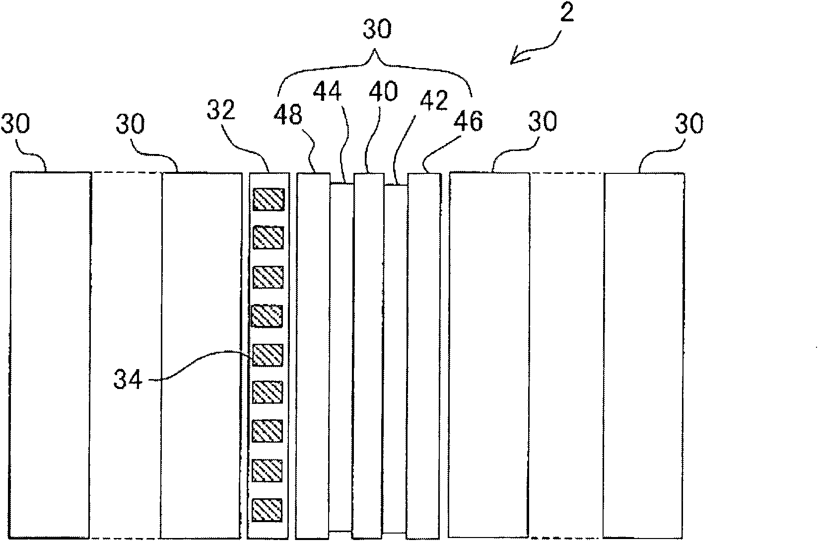
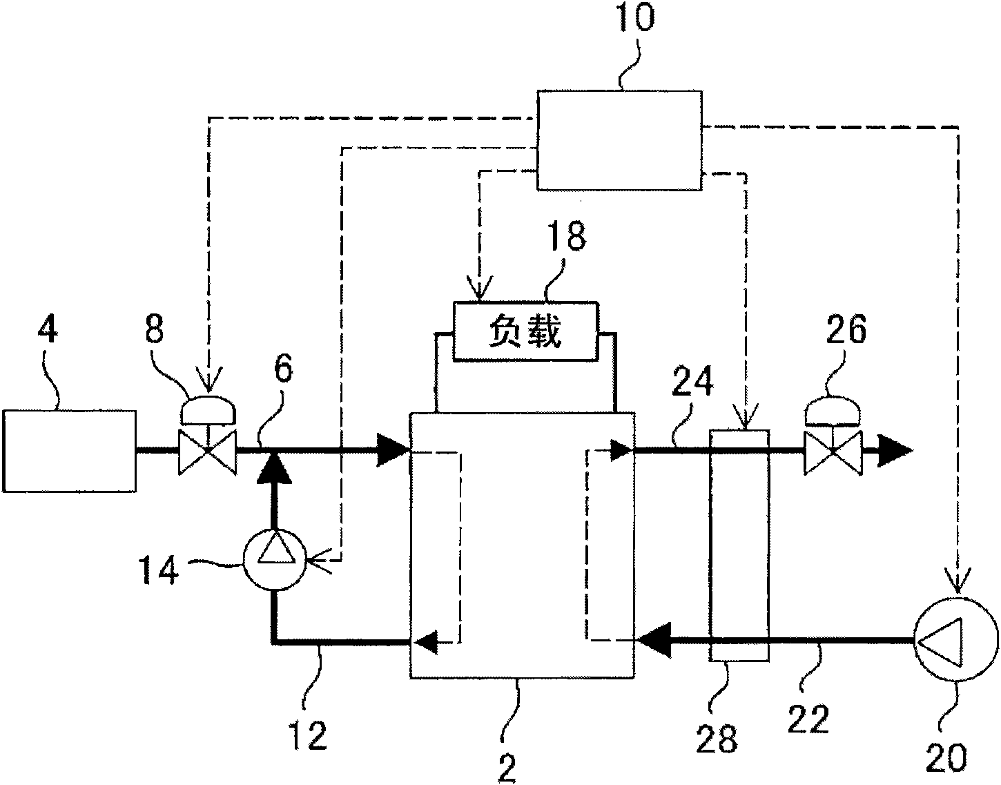
[0063] figure 1 It is a diagram schematically showing the configuration of the fuel cell system in this embodiment. Such as figure 1 As shown, the fuel cell is used by stacking a plurality of unit cells 30 to form the fuel cell stack 2 . The unit cell 30 is configured such that a membrane electrode assembly (MEA) 40 is sandwiched between a pair of current collector plates 46 and 48 . The collector plates 46 and 48 also function as separators for separating two adjacent membrane electrode assemblies. A cathode gas flow channel 42 for supplying air to the membrane electrode assembly 40 is formed inside the cathode side collector plate 46 . An anode gas flow channel 44 for supplying hydrogen gas to the membrane electrode assembly 40 is formed inside the anode side collector plate 48 .

[0064] In the fuel cell stack 2, the current measurement unit 32 and the unit cel...

Embodiment approach 2

[0105] Next, Embodiment 2 of the present invention will be described using the drawings.

[0106] The fuel cell system of the present embodiment differs from the first embodiment in the flow direction of the reactant gas in the fuel cell stack 2 . The fuel cell stack 2 of the present embodiment is configured such that the flow direction of air in the cathode gas flow channel 42 and the flow direction of hydrogen gas in the anode gas flow channel 44 are the same direction, that is, air and hydrogen gas flow in parallel. Due to the difference in the flow direction of the reactant gas, the method of abnormality diagnosis based on the measurement signal of the current measurement unit 32 is also different in the fuel cell system of the present embodiment and the fuel cell system of the first embodiment.

[0107] Figure 8 and Figure 9 It is a diagram in which the signals of the respective current sensors 34 included in the current measuring unit 32 are arranged in the flow dire...


PUM


Abstract

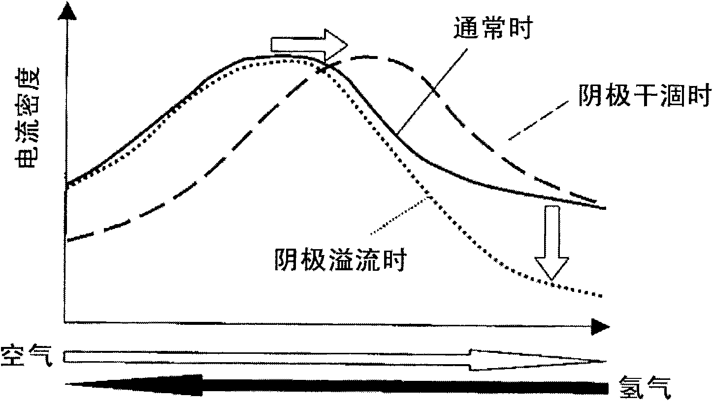
It is possible to perform a detailed diagnosis of a dry degree inside a fuel cell in a fuel cell system. Distribution of a current density on an electricity generation plane of a fuel cell is measured and the dry degree inside the fuel cell is diagnosed according to a change of a current density peak position on the electricity generation plane. When the fuel cell is a type in which a reaction gas (hydrogen) of the anode side and a reaction gas (air) of the cathode side flow to oppose to each other so as to sandwich the generation plane, it is judged whether the current density peak position is changed toward an anode exit or a cathode exit. Thus, it is possible to judge whether a dry-up is generated in the anode side or the cathode side according to the judgment result.

Description

technical field [0001] The present invention relates to a fuel cell system, and more specifically, to a fuel cell system that diagnoses a dry state inside a fuel cell and reflects the diagnosis result to system control. Background technique [0002] For a long time, various patent documents such as Japanese Patent Application Publication No. 2006-318784, Japanese Patent Application Publication No. 2005-100952, and Japanese Patent Application Publication No. 9-259913 have disclosed that a multi- current sensors, and reflect the measurement results of the local currents measured by these current sensors to the system control. In the techniques disclosed in these patent documents, the measured value of the local current at each measurement point is compared with a predetermined reference value individually, or the model of the current distribution obtained by integrating the measured values ​​is compared with a predetermined reference model. . Then, from these comparison resu...

Claims


Application Information

Patent Timeline
Patent Type & Authority Applications(China)
IPC IPC(8): H01M8/04H01M8/10
CPCH01M8/04179H01M8/04268H01M8/04529H01M8/04097H01M8/04574H01M8/04582H01M8/04828H01M8/04589Y02E60/50H01M8/04141H01M8/04492H01M8/0485
Inventor 末松启吾
Owner TOYOTA JIDOSHA KK
Learn More