Helical motion type pipeline surface cleaning mechanical arm

A surface cleaning and moving technology, applied in the direction of cleaning hollow objects, cleaning methods and utensils, chemical instruments and methods, etc., can solve the problems of high cost, time-consuming and low efficiency of equipment and use, and achieve convenient and easy installation , clean up thoroughly

Inactive Publication Date: 2011-01-05
SHENYANG JIANZHU UNIVERSITY
View PDF3 Cites 46 Cited by
  • Summary
  • Abstract
  • Description
  • Claims
  • Application Information

AI Technical Summary

Problems solved by technology

At present, when cleaning the anti-corrosion layer in our country, manual removal is basically used, which is inefficient, time-consuming, laborious, and affects the physical condition of workers.
The United States adopts high-temperature and high-pressure air blowing method. Although it is more convenient to clean up by hand, the cost of equipment and use is very high.

Method used


Image

  • Helical motion type pipeline surface cleaning mechanical arm
  • Helical motion type pipeline surface cleaning mechanical arm
  • Helical motion type pipeline surface cleaning mechanical arm

Examples


Embodiment 1

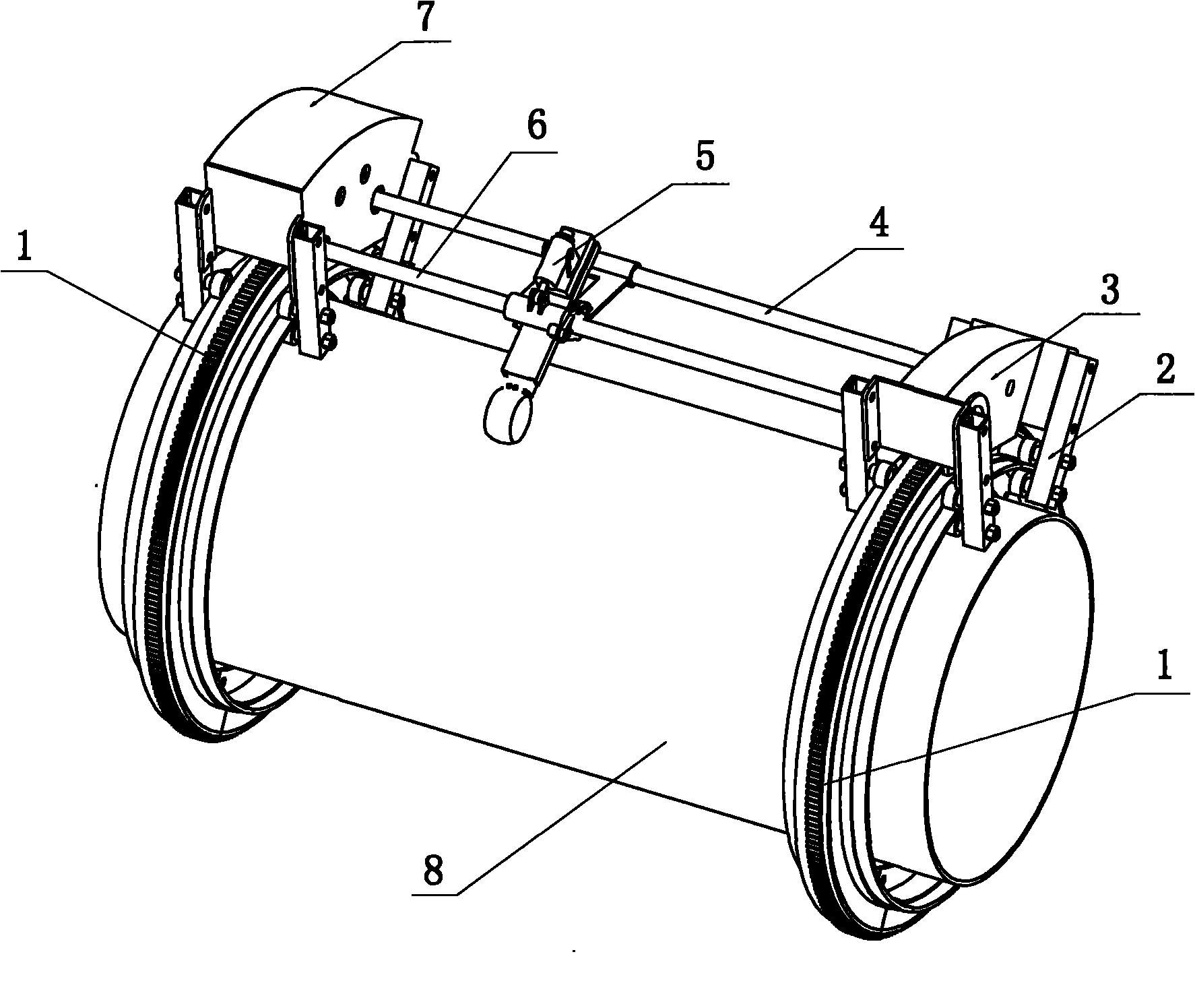
[0044] Embodiment 1: as Figure 1 ~ Figure 4 As shown, the present invention includes ring gear track 1, support 2, driving box 3, driven box 7, lead screw 6, feed rod 4, working device 5 and power supply device 9, and described ring gear track 1 is two, respectively Fixed on the pipeline by bolts, the active box 3 and the driven box 7 are respectively supported on the ring gear track 1 through the bracket 2 with rollers, the first gear in the active box 3 connected with the output shaft of the motor reducer is installed on the light The second gear at one end of the bar and the fourth gear on the input shaft in the driven box 7 mesh with the ring gear track 1 respectively, and rotate relatively along the ring gear track 1. The other end of the light rod 4 is connected with the input shaft of the driven box 7. One end of the leading screw 6 is connected with the output shaft of the driven box, and the other end is supported on the casing of the driving box. The leading screw 6...

Embodiment 2

[0054] Embodiment 2: The overall structure of this embodiment is the same as that of Embodiment 1, the difference is that the steel brush wheel 505 described in this embodiment is a steel brush. There are 3 adjusting legs on the ring gear track 1, which are evenly distributed on the ring plate 105 of the inner wall 104 of the track frame; the ring track 901 legs 910 of the power supply device 9 are 4, which are evenly distributed on the ring connecting plate 906 superior.

Embodiment 3

[0055] Embodiment 3: The overall structure of this example is the same as that of Embodiment 1, the difference is that in this example, there are 5 adjusting legs on the ring gear track 1, which are evenly distributed on the annular plate 105 of the inner wall 104 of the track frame; There are five supporting legs 314 of the power supply device 305 in the box 3, which are evenly distributed on the annular connecting plate 313 thereof.


PUM


Abstract

The invention provides a helical motion type pipeline surface cleaning mechanical arm. The mechanical arm comprises gear ring rails, a bracket, a drive case, a driven case, a screw rod, a feed rod, a working device and a power supply device, wherein the gear ring rails are two; the drive case and the driven case are arranged on the gear ring rails through the bracket with a roller respectively; a first gear connected with an output shaft of a motor reducer in the drive case, a second gear arranged at one end of the feed rod and a fourth gear on an input shaft in the driven case are engaged with the gear ring rail respectively, and rotate relatively along the gear ring rail; the other end of the feed rod is connected with the input shaft of the driven case; one end of the feed rod is connected with the output shaft of the driven case, while the other end is supported against the body of the drive case; the screw rod and the feed rod are parallel with each other; the working device is arranged on the screw rod and the feed rod, and translates along the screw rod and the feed rod; and the drive case and the working device are connected with the power supply device respectively. The mechanical arm can automatically clean the anticorrosion layer on the pipeline surface, saves time and power, and is suitable for maintenance and cleaning of petroleum pipelines, natural gas pipelines and the like.

Description

technical field [0001] The invention relates to a spiral motion type pipe surface cleaning manipulator. Background technique [0002] Oil and natural gas pipelines are coated with modified asphalt and other anti-corrosion layers on the surface for anti-corrosion. When the pipeline leaks, the anti-corrosion layer on the surface needs to be removed for plugging. At present, when cleaning the anti-corrosion layer in our country, manual removal is basically adopted, which is inefficient, time-consuming, laborious, and affects the physical condition of workers. The United States adopts high-temperature, high-pressure air blowing method, although it is more convenient to clean up by hand, but the cost of equipment and use is very high. [0003] The purpose of the present invention is to provide a manipulator that can automatically remove the anti-corrosion layer on the surface of the pipe, realize the high efficiency and low consumption of the anti-corrosion layer removal work on...

Claims


Application Information

Patent Timeline
Patent Type & Authority Applications(China)
IPC IPC(8): B08B9/023
Inventor 李斌廖颖哲洪晋平
Owner SHENYANG JIANZHU UNIVERSITY
Why Eureka
Try Eureka