Disc brake for belt conveyor

A technology of disc brakes and belt conveyors, applied in conveyors, underground transportation, transportation and packaging, etc., can solve problems such as short service life of brakes, jamming phenomenon, easy loosening of nuts, etc., to ensure sealing performance and use Life, avoid jamming phenomenon, ensure the effect of flexibility

Inactive Publication Date: 2011-01-05
CHINA UNIV OF MINING & TECH +1
View PDF6 Cites 5 Cited by
  • Summary
  • Abstract
  • Description
  • Claims
  • Application Information

AI Technical Summary

Problems solved by technology

However, the braking torque of the down belt conveyor is very large, and the radial force generated on the piston is far beyond its allowable range, thus causing the following four problems: 1) The brake action is not flexible, and jamming often occurs Phenomenon; 2) The service life of the brake is short, and it usually starts to fail within 5 to 7 months; 3) The brake cylinder leaks oil, which cannot guarantee the gap between the brake and the brake disc, making the brake disc in a state of friction for a long time , the temperature rises, it is easy to cause gas explosion; 4) due to oil leakage and damage to parts, the brake locks the brake disc when the brake needs to be released, causing the conveyor belt to tear, causing major safety accidents and even casualties
At present, foreign countries have adopted methods of improving machining accuracy and new composite materials to solve the above problems, but the cost is too high, which is more than ten times the price of traditional brakes, and there are great difficulties in popularization and application.
In addition, there is no anti-loosening measure for the adjusting nut of the traditional structure, and the adjusting nut is easy to loosen during the working process, resulting in a reduction of the braking force, which cannot ensure safe braking

Method used


Image

  • Disc brake for belt conveyor
  • Disc brake for belt conveyor
  • Disc brake for belt conveyor

Examples


Embodiment Construction

[0010] An example of the present invention will be further described below in conjunction with accompanying drawing:

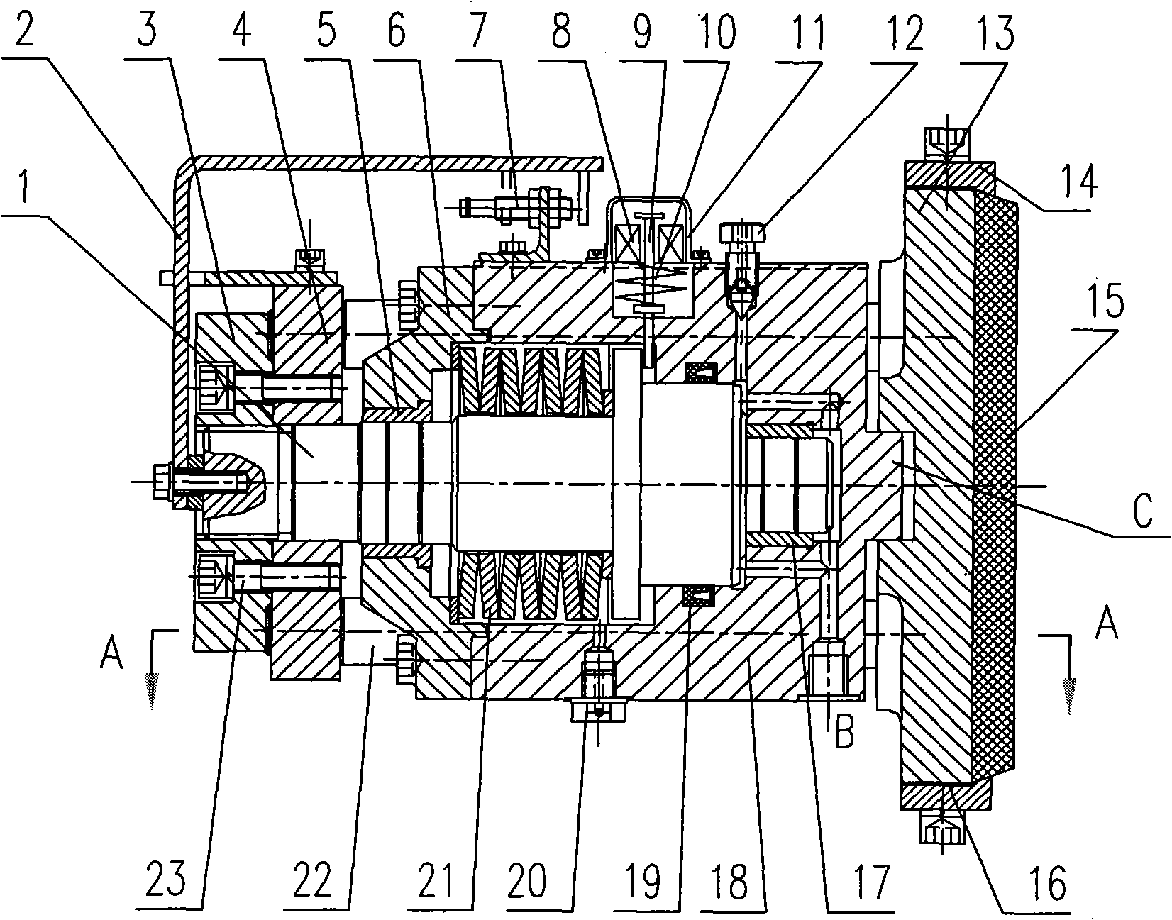
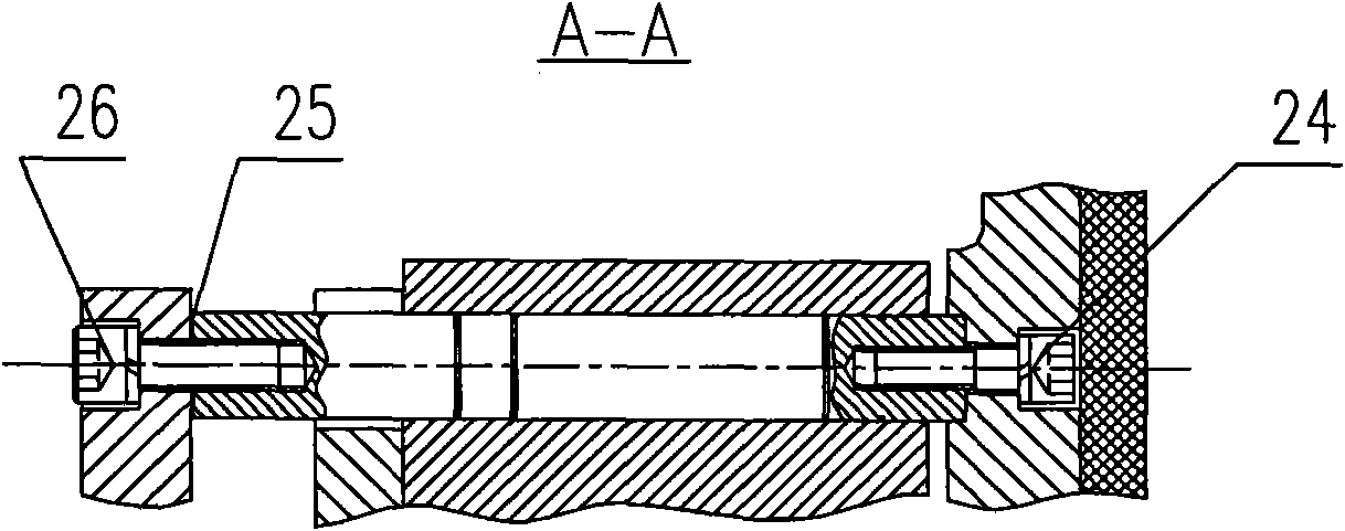
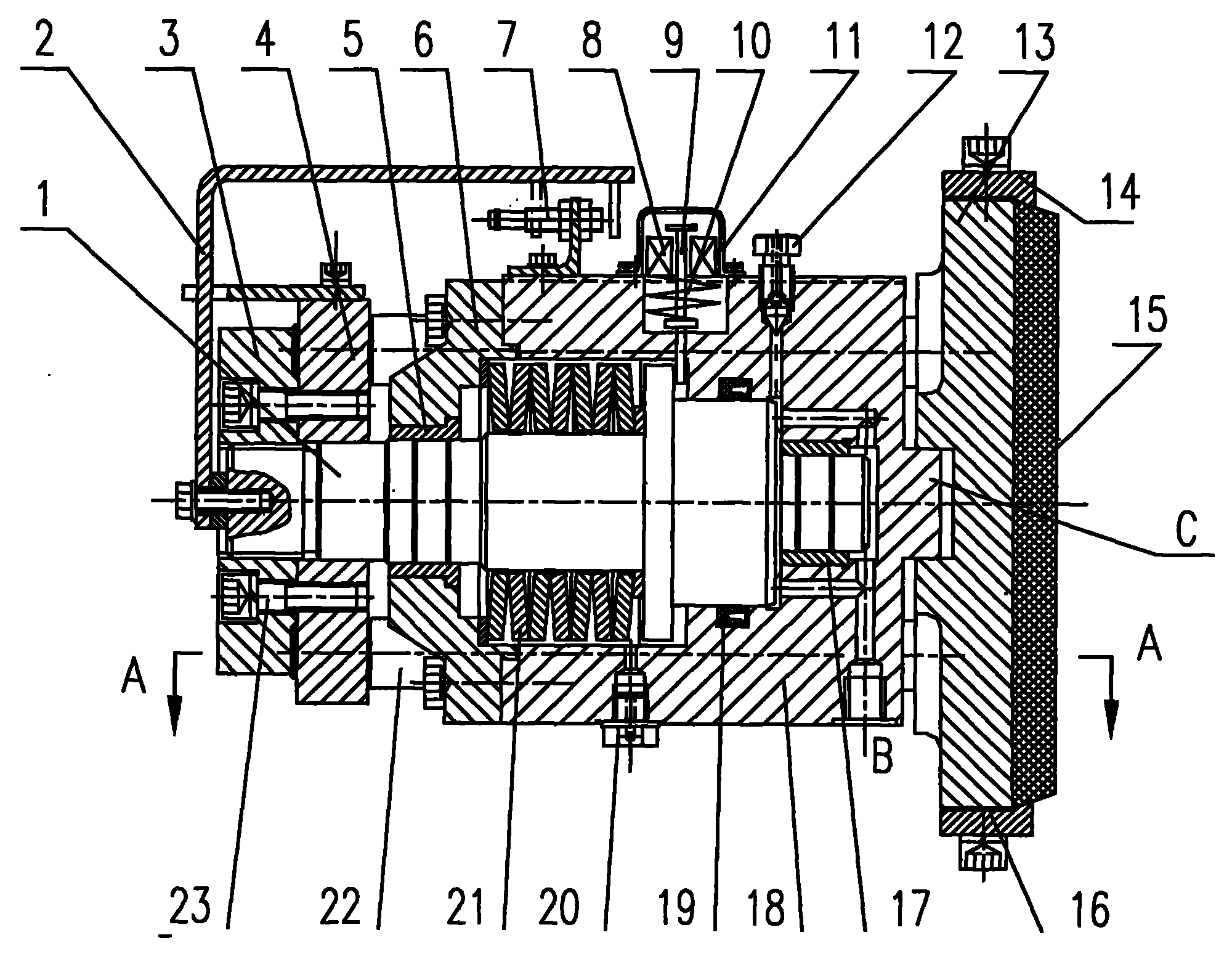
[0011] figure 1 As shown, the belt conveyor disc brake of the present invention is mainly composed of a piston 1, a displacement indicator plate 2, an adjustment nut 3, a thrust plate 4, a cover plate 6, a displacement sensor 7, a brake shoe support seat 13, a brake seat 18, Brake shoe 15, disc spring 21, cover plate 6, support column 22 and the protective device of abnormal braking are formed. Among them: the butterfly spring 21 is set on the piston 1 and installed in the brake seat 18 together. The brake shoe 15 is connected with a brake shoe support seat 13 with a groove in the middle. The upper and lower parts of the brake shoe 15 and the brake shoe support seat 13 are provided with The brake shoe pressing plate 14 which is fixed together, the brake shoe 15 is fixed on the brake shoe support seat 13 through the brake shoe pressing plate 14, and the matchi...


PUM


Abstract

The invention relates to a disc brake for a belt conveyor, which comprises a piston, a brake shoe, a brake carrier, a disc spring and a displacement sensor, wherein the brake shoe is fixed in a brake shoe support seat, the middle part of the brake shoe support seat is a groove, a stepped blind hold is formed on one side of the brake carrier, an end face key is arranged at the middle part at one end on the side of the blind hole of the brake carrier, a cover plate is fixedly arranged at the open end of the brake carrier, a thrust plate is sheathed on the tail part of the piston, support pillars penetrating the brake carrier are symmetrically fixedly arranged above and below the thrust plate, the other end of each support pillar is fixed on the brake shoe support seat, and the piston is not directly linked with the brake shoe support seat, but is linked with the brake shoe support seat through a regulating nut, the thrust plate and the support pillars. The brake shoe support seat is linked with the brake carrier through the end face key, and the braking force is transferred to the brake carrier through the end face key and further transferred to a frame, thereby leading the piston to be free of any radial force. A flange of the piston and a brake carrier hole adopt a positioning steel sheet which is pressed in by relying on spring force under the brake releasing state, thereby preventing the abnormal brake and having the advantages of compact structure, reliable performances, convenient regulation, good braking effect and low cost.

Description

technical field [0001] The invention relates to a disc brake of a belt conveyor, in particular to a brake suitable for braking a belt conveyor under a large inclination angle in a coal mine. Background technique [0002] The braking of the down-conveying belt conveyor with large inclination angle in the coal mine plays a vital role in the service life of the belt conveyor and the safety of the equipment and personnel in the coal mine. At present, such brakes at home and abroad generally adopt disc brakes, but the brakes still adopt the traditional structure, that is, the brake shoe is directly installed at one end of the piston, and the piston bears a large dynamic radial force during braking. This structure is suitable for equipment with small braking torque. At this time, the radial force on the piston is small, and the damage to the seal and other parts is small. However, the braking torque of the down belt conveyor is very large, and the radial force generated on the pi...

Claims


Application Information

Patent Timeline
Patent Type & Authority Applications(China)
IPC IPC(8): B65G23/26E21F13/00
Inventor 孟庆睿侯友夫吴宏志
Owner CHINA UNIV OF MINING & TECH
Why Eureka
Try Eureka