Backlight module

A backlight module and backplane technology, applied in optics, light guides, light sources, etc., can solve the problems of difficult heat dissipation, low proportion of light-emitting diodes, and increase the manufacturing cost of backlight modules, and achieve the effect of reducing manufacturing costs and improving the heat dissipation environment.

Active Publication Date: 2011-01-05
TCL CHINA STAR OPTOELECTRONICS TECH CO LTD
View PDF5 Cites 10 Cited by
  • Summary
  • Abstract
  • Description
  • Claims
  • Application Information

AI Technical Summary

Problems solved by technology

Therefore, the ratio of the actual number of light-emitting diodes used to the total production quantity is too low, which relatively increases the manufacturing cost of the backlight module.
[0004] Furthermore, the LED strips currently used in backlight modules are all arranged at equal intervals. When the light strips are driven to emit light, the LEDs located in the center of the light strips are bound to be larger than those located in the center of the light strips. The light-emitting diodes at both ends of the light bar are not easy to dissipate heat. Since the temperature difference has a great influence on the luminous efficiency of the light-emitting diodes, the phenomenon of uneven heat distribution will affect the uniformity of the overall light emission of the backlight module. The light-emitting diodes in the central position also have a relatively short working life

Method used


Image

  • Backlight module
  • Backlight module
  • Backlight module

Examples


Embodiment Construction

[0033] In order to make the above objects, features and advantages of the present invention more comprehensible, preferred embodiments of the present invention are exemplified below and described in detail in conjunction with the accompanying drawings. Furthermore, the directional terms mentioned in the present invention, such as "up", "down", "front", "rear", "left", "right", "inside", "outside", "side", etc., Just refer to the direction of the attached drawing. Therefore, the directional terms used are used to illustrate and understand the present invention, but not to limit the present invention.

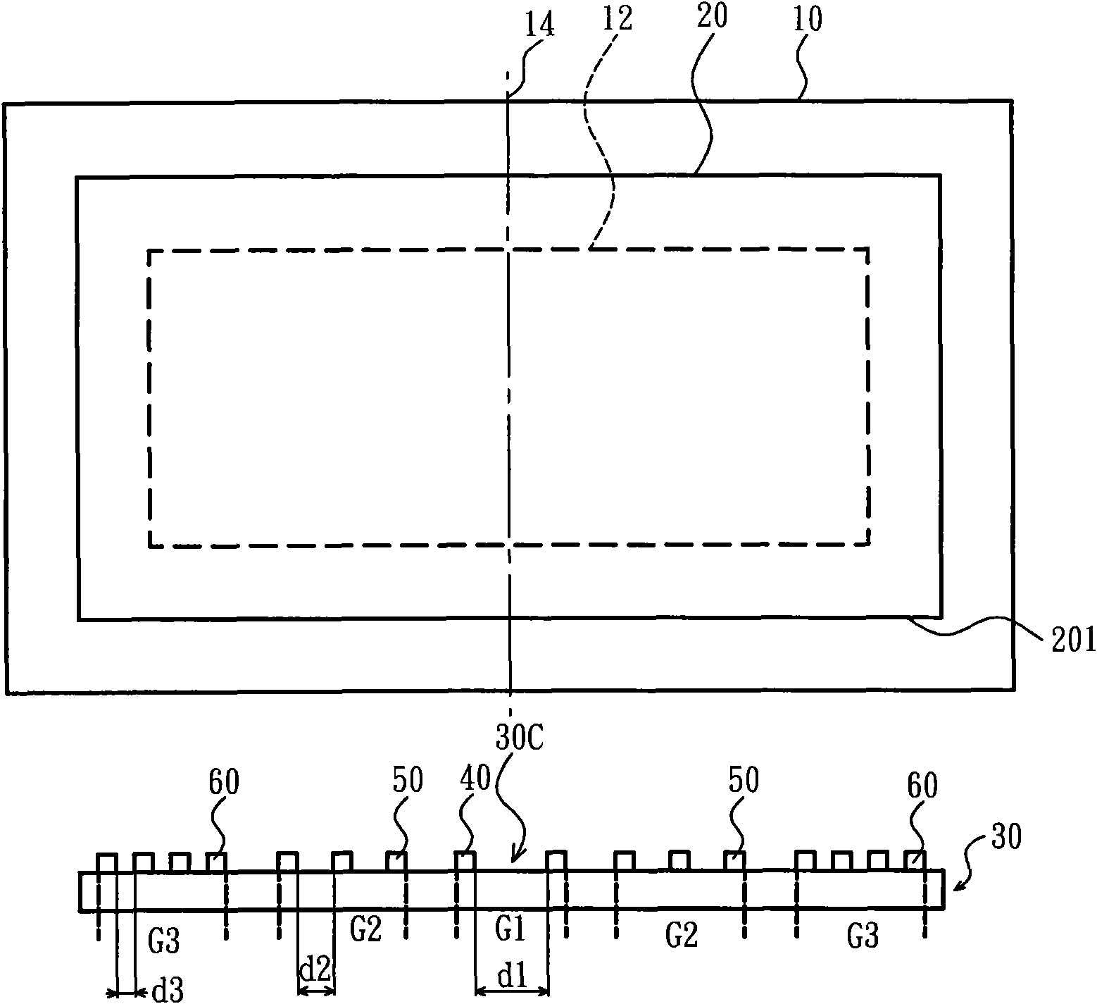
[0034] Please refer to Figure iA, Figure 1A It discloses the schematic diagram of the first embodiment of the backlight module of the present invention, wherein the backlight module of the first embodiment of the present invention is a side entry type backlight module. In this embodiment, the backlight module includes a backplane 10 , a light guide plate 20 , a light bar group ...


PUM


Abstract

The invention discloses a backlight module which comprises a plurality of LEDs. The LEDs are grouped into a plurality of lamp groups according to the distances between two adjacent LEDs, the plurality of LEDs are provided with a position center corresponding to a central line of a display area, the lamp groups with a larger LED distance relatively approach to the position center and have a higherbrightness level, and the lamp groups with a smaller LED distance are relatively far from the position center and have a lower brightness level. Accordingly, the luminescent conditions of the whole LEDs trend to be consistent, and the proportion of adopting the LEDs with different brightness levels is increased.

Description

【Technical field】 [0001] The present invention relates to a backlight module, in particular to a backlight module in which light emitting diodes are arranged according to the heat dissipation conditions of the positions of the light emitting diodes and the brightness level (bright bin) of the light emitting diodes. 【Background technique】 [0002] A liquid crystal display (LCD) is mainly composed of a backlight module and a liquid crystal panel. Compared with other display devices, it has the advantages of lightness, thinness, low driving voltage and low power consumption, and has been widely used in the display industry. Currently, the types of backlight modules can be mainly divided into light emitting diode (LED) backlight modules and cold cathode fluorescent tube (CCFL) backlight modules. Since LED backlight modules have the advantage of low power consumption, replacing cold cathode fluorescent tube backlight modules with LED backlight modules has become the mainstream tr...

Claims


Application Information

Patent Timeline
IPC IPC(8): F21S8/00F21V19/00F21V8/00G02F1/13357F21Y101/02
CPCG02F1/133603G02F2001/133613F21V19/00F21S8/00G02F1/133613
Inventor 曹谦林博瑛
Owner TCL CHINA STAR OPTOELECTRONICS TECH CO LTD
Why Eureka
Try Eureka