Image recovery strengthening method for space-based wide-view field imaging point source/spot target

一种图像恢复、大视场的技术,应用在交叉科学领域,能够解决模糊等问题

Inactive Publication Date: 2011-01-05
HUAZHONG UNIV OF SCI & TECH
View PDF3 Cites 12 Cited by
  • Summary
  • Abstract
  • Description
  • Claims
  • Application Information

AI Technical Summary

Problems solved by technology

However, it may also fall on 2 to 4 photosensitive elements (as shown in Figure (3b) to Figure (3d)). At this time, these photosensitive elements all respond, making a point image into a point image of 2 to 4 pixels. blur effect

Method used


Image

  • Image recovery strengthening method for space-based wide-view field imaging point source/spot target
  • Image recovery strengthening method for space-based wide-view field imaging point source/spot target
  • Image recovery strengthening method for space-based wide-view field imaging point source/spot target

Examples


Embodiment Construction

[0046] Below in conjunction with accompanying drawing and example the present invention is described in further detail.

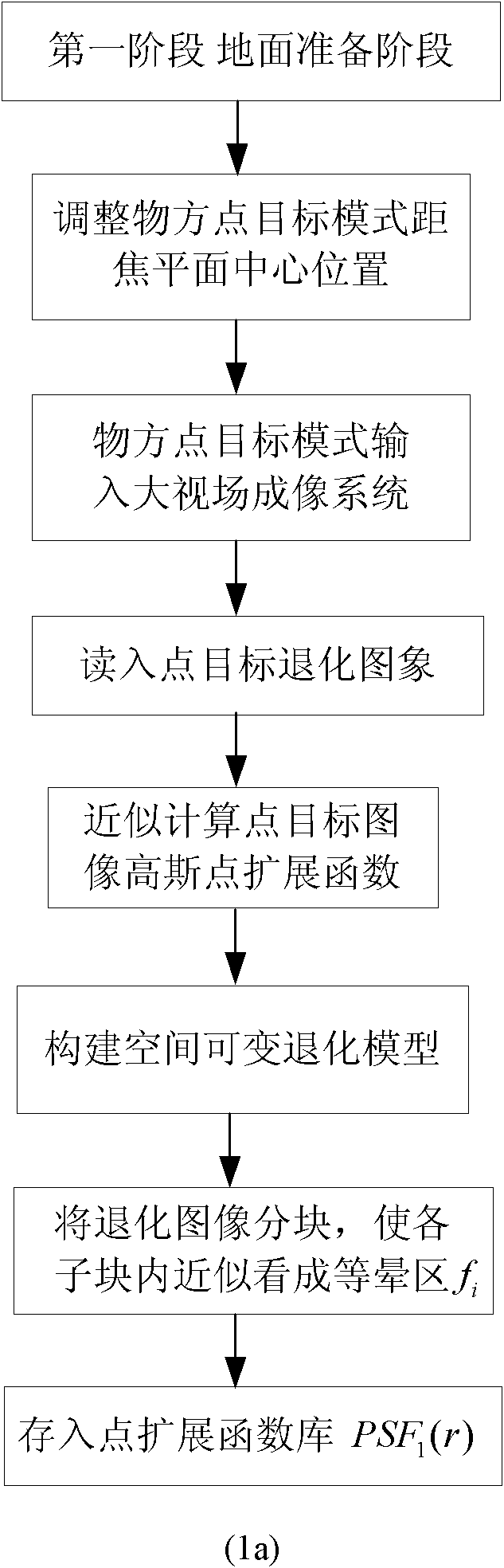
[0047] Ground preparation phase:

[0048] (1) Divide the spatially variable degraded image of the imaging sensor device due to the limitation of the design and manufacturing process technology level into multiple spatially invariant image sub-blocks, and construct the overall point spread function of each image sub-block.

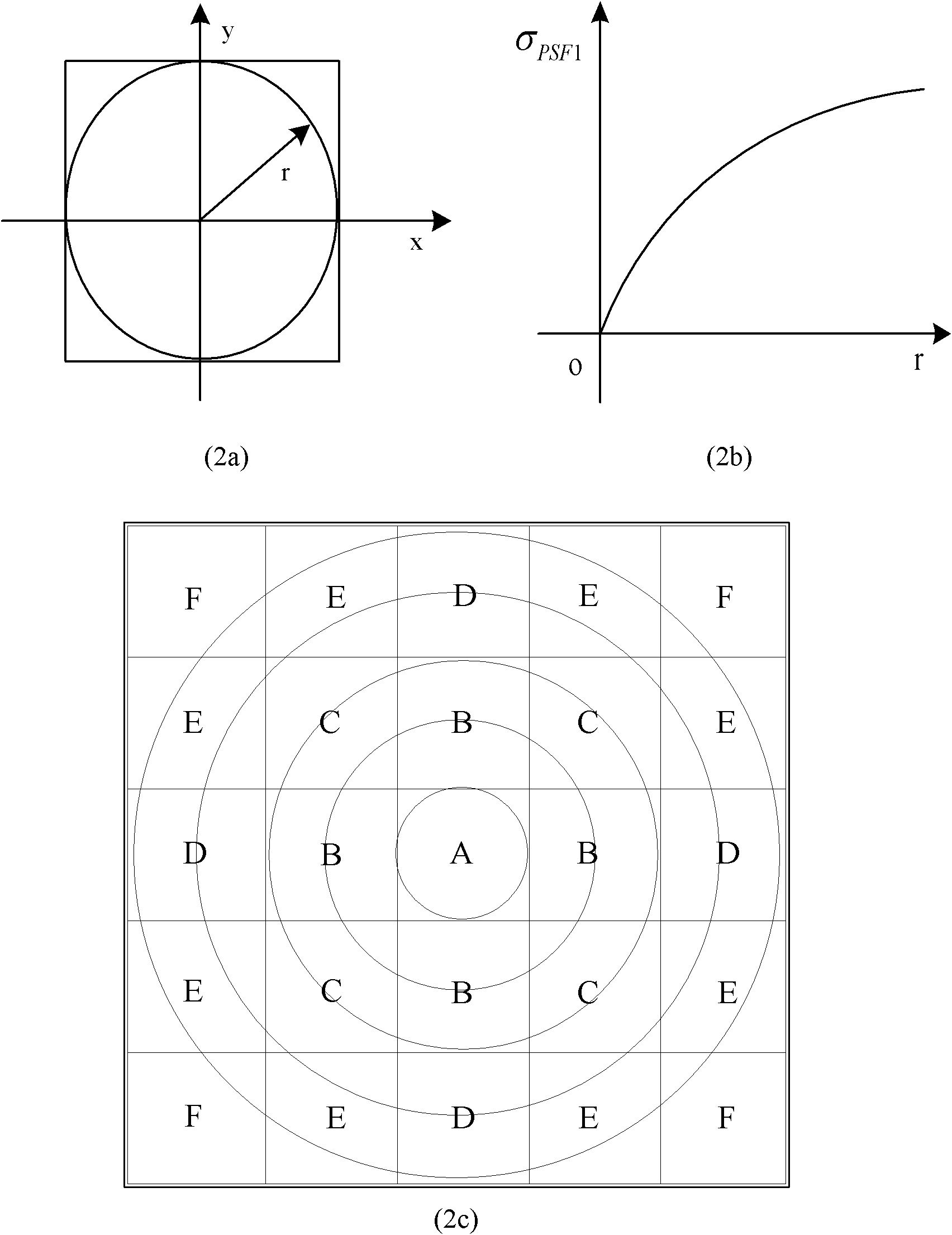
[0049] (1.1) According to the distance between the photosensitive element and the lens axis, the grayscale image on the focal plane, that is, the spatially variable degraded image, is divided into M sub-blocks (the value of M is determined according to the distance between the photosensitive element and the lens axis, generally 1× A degraded image with a size from 1 to 32×32 can be considered to be spatially invariant, so M can be taken as the size of the input image divided by 32×32), and each image sub-block is represented by f i (i i...


PUM


Abstract

The invention discloses a recovery strengthening method for a space-based wide-view field imaging point source / spot target, which comprises the following steps of: (1) dividing a space variable degraded image into a plurality of space invariable image subblocks and constructing a point spreading function of all the image subblocks; (2) dividing the degraded image into a plurality of space approximate invariable image subblocks and measuring PSFil(r) off line on the ground; (3) correcting all the image subblocks by utilizing a maximum likelihood algorithm; and (4) splicing all the image subblocks by a splicing algorithm and finishing correction on the degraded image. The invention establishes a space variable point spreading function model of a wide-view field imaging sensor and provides and realizes a space variable recovery correcting method and can effectively realize the recovery strengthening of the point source / spot target.

Description

technical field [0001] The invention belongs to the field of interdisciplinary science and technology combining aerospace technology and image processing, and in particular relates to a restoration and enhancement method for space-based large field of view imaging point source / spot-shaped target. Background technique [0002] During space-based earth observation, due to limitations in the design of imaging detection equipment and the technical level of manufacturing technology, image quality will be reduced, such as image distortion or blurring. Especially for speckle / point targets, the signal of point sources or speckle targets will be weakened, resulting in missed detection of point source targets or speckle targets with weak signals. The blur produced by the imaging sensor itself can be approximated by a point spread function model. However, the spatially invariant point spread function degradation model used in traditional small field of view imaging sensors cannot accu...

Claims


Application Information

Patent Timeline
Patent Type & Authority Applications(China)
IPC IPC(8): G06T5/00
CPCG06T2207/30181G06T2207/20021G06T5/00G06T2207/10032G06T5/003G06T5/73
Inventor 张天序武道龙陈建冲关静余铮陈浩左芝勇张蒲涛
Owner HUAZHONG UNIV OF SCI & TECH
Why Eureka
Try Eureka