Clamping welding machine head

A machine head and welding machine technology, applied in welding equipment, resistance welding equipment, metal processing equipment, etc., can solve problems such as uncontrollable gaps, poor welding, bending deformation, etc., to improve stability and authenticity, improve Improvement of welding quality and overall rigidity

Active Publication Date: 2011-01-12
镇江泛沃新能汽车技术股份有限公司
View PDF5 Cites 14 Cited by
  • Summary
  • Abstract
  • Description
  • Claims
  • Application Information

AI Technical Summary

Problems solved by technology

This moment, the two ends of this auxiliary frame 22 become a cantilever beam, and overall rigidity is poor
The length of the left end is much longer than that of the right end, and the end is fixed with parts such as cylinders. If it is subjected to external force, it is easy to bend and deform, and the left and right linear guides 20 will also deform accordingly. On the one hand, it will cause movement. The left electrode does not correspond to the fixed right electrode, and cannot form a common clamping point and welding point
On the other hand, the guide rail 20 will generate torque when the electrode 18 is under pressure, so that the guide post 20 cannot slide smoothly in the left and right linear bearings 21, or even get stuck, so that when the clamping cylinder 16 is working, the adjustment pressure spring 23 It does not work, the pressure displayed by the pressure sensor is distorted, resulting in the clamping force of the cylinder not being applied to the welding point, and the pressure sensor of this mechanism cannot sense the clamping pressure of the two electrodes equally, so that the welder cannot perform proper clamping welding
[0004] In addition, there is a problem of adjusting the relative position of the electrode and the weldment. When the weldment is clamped and positioned, the head of the welding machine moves down to the working position with the auxiliary frame 22. In this solution, the electrode 18 is a movable electrode, which can be clamped and moved in the horizontal direction. , the electrode 19 is a fixed

Method used


Image

  • Clamping welding machine head
  • Clamping welding machine head
  • Clamping welding machine head

Examples


Embodiment Construction

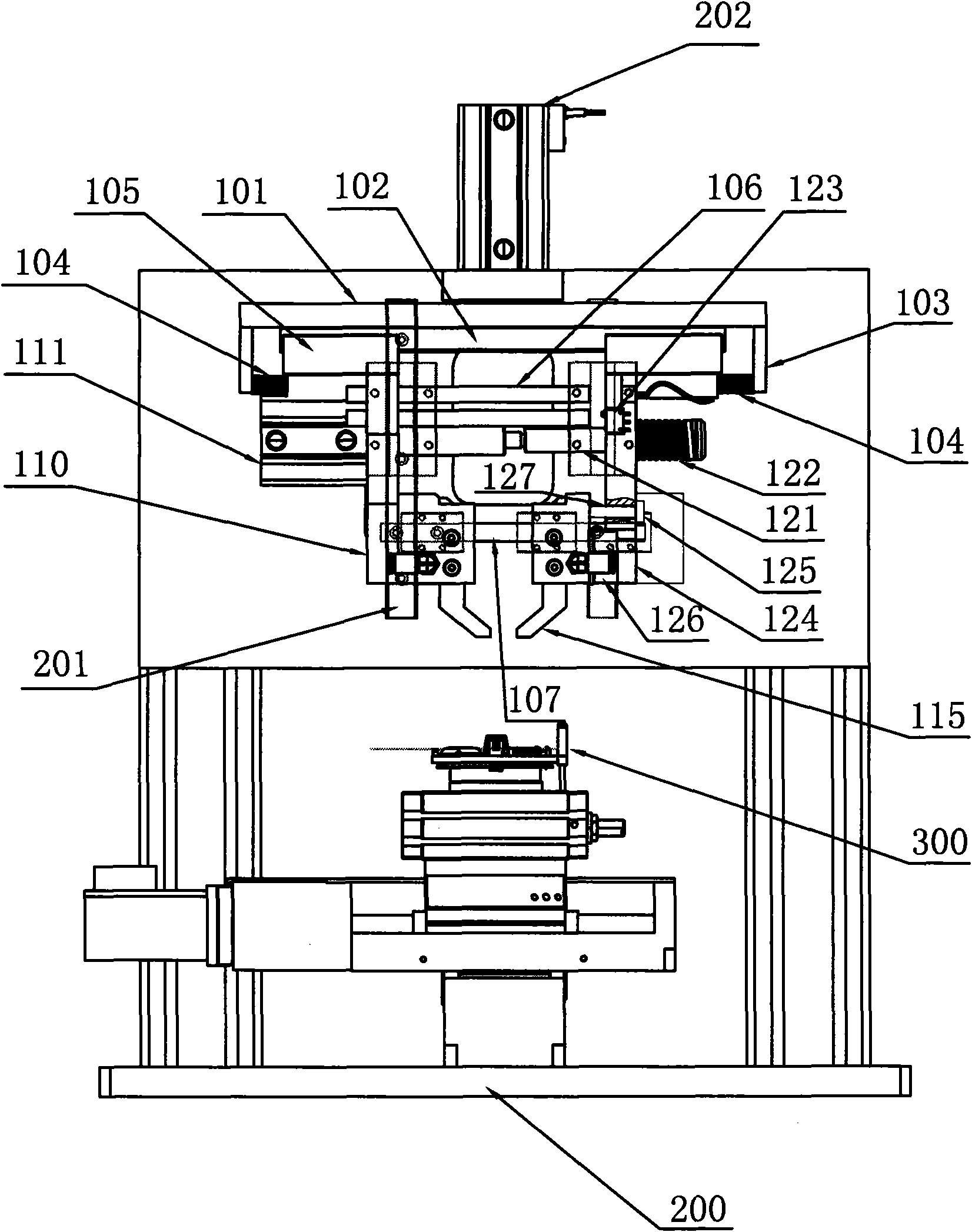
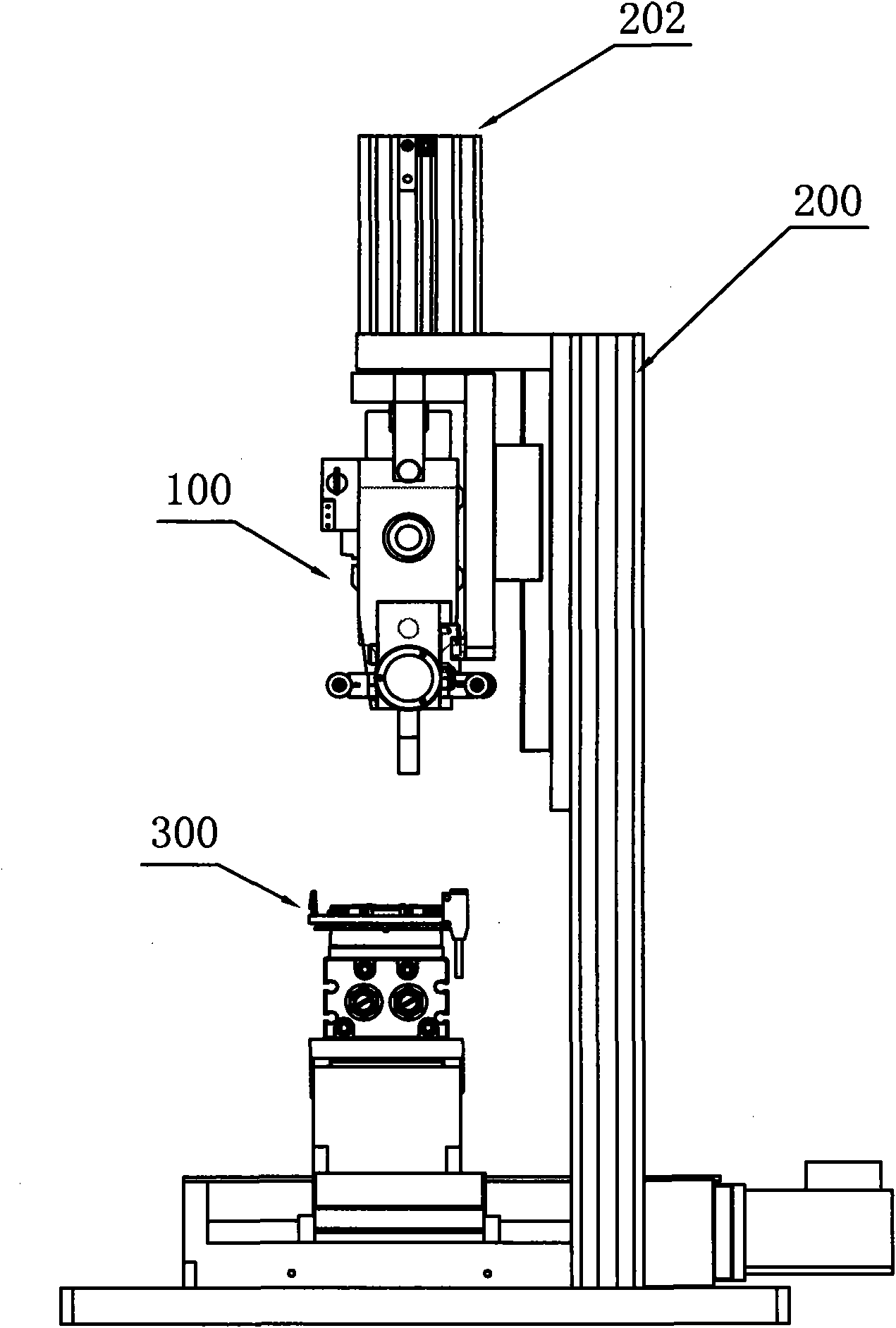
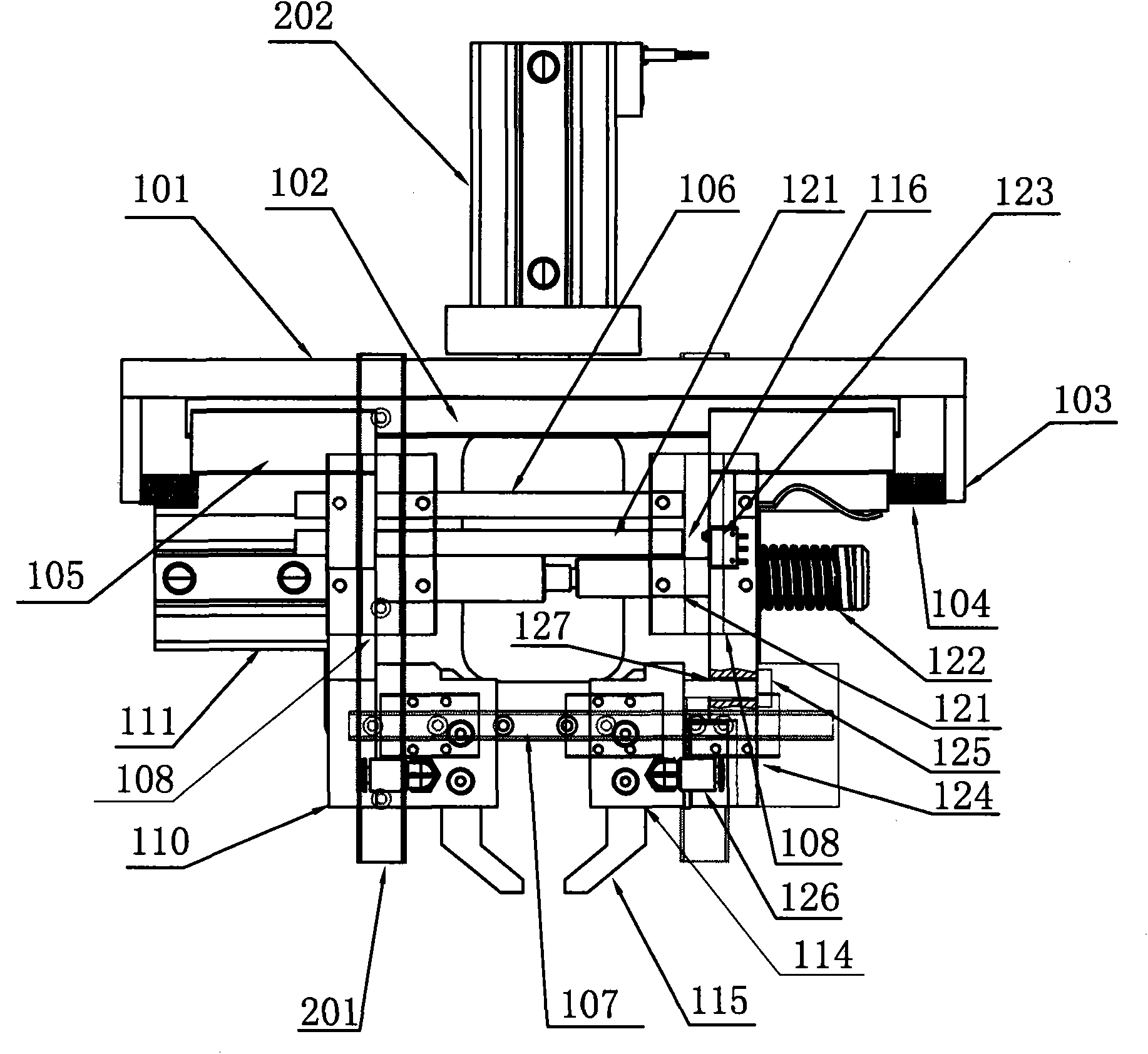
[0021] control figure 1 , welding machine head 100 of the present invention is mainly made of clamping frame 101, guide rail 102, two supports 110, two balance springs 103, two electrodes 115, cylinder 111 (or servo motor), pull rod 121, feedback board 116, displacement sensor 123, compression spring 122 and pressure sensor 124 form. The machine head 100 is slidably connected with the vertical guide rail 201 on the resistance welding machine frame 200 through two vertically distributed and spaced sliders 108 on the rear side of the clamping frame 101, so that the clamping frame 101 is placed horizontally. The piston rod of the cylinder 202 fixed on the welding machine frame 200 is connected with the upper end of the clamping frame 101, and pushes the welding machine head 100 to move up and down along the vertical guide rail 201 through telescopic movement.

[0022] The lower side of the upper end plate of the clamping frame 101 is provided with a guide rail 102, and two slid...


PUM


Abstract

The invention relates to a clamping welding machine head which comprises a cylinder, a holddown spring, a pressure sensor, a displacement sensor, two electrodes, a horizontal clamping machine frame, a draw rod, a feedback plate, two balancing springs, two brackets and two sliding blocks, wherein the clamping machine frame is provided with a guide rail; the two sliding blocks are respectively connected on the guide rail in a sliding mode; the two brackets are respectively connected to the sliding blocks; each bracket is connected by the balancing spring and the corresponding end of the clamping machine frame; the two electrodes are respectively fixedly and movably connected to the corresponding brackets; the feedback plate and the displacement sensor are respectively connected to one bracket; the pressure touch rod of the pressure sensor is installed on the electrode which is movably connected to the bracket, or the corresponding bracket; the cylinder is fixed on one bracket; the draw rod penetrates through and is sleeved on the other bracket; the end part of the piston rod of the cylinder is coaxially connected with the inner end of the draw rod; and when the piston rod contracts or extends, the cylinder drives the two brackets to make a closing or departing motion. The invention has the advantages of favorable rigidity, convenient and quick adjustment of positions of electrodes and weldments, and high welding quality.

Description

technical field [0001] The invention relates to welding equipment, in particular to a resistance clamp welding machine head for multi-point clamp welding of small metal objects. Background technique [0002] The applicant of the present application provided a high-performance resistance welding equipment for the unstable welding quality existing in the existing resistance welding equipment, and applied for a utility model patent, which was authorized (publication number CK201446354U). This patent adopts high-precision pressure sensor, high-precision displacement sensor and tracking system to collect pressure signal and displacement signal, and controls the whole process of welding of metal workpieces through programmable controller program control, so as to ensure stable welding quality. However, there are still some parts to be improved in the structural design of the welding equipment. The following is some analysis on its deficiencies: [0003] Please see attached Figur...

Claims


Application Information

Patent Timeline
IPC IPC(8): B23K11/11B23K11/36
Inventor 张荣成
Owner 镇江泛沃新能汽车技术股份有限公司
Why Eureka
Try Eureka