Navigation-hydraulic motor-driven device

A technology for motorized devices and navigation, which is used in transportation and packaging, ship propulsion, and ship parts, etc. It can solve problems such as consumption and large energy consumption, and achieve the effect of reducing friction and increasing negative pressure resistance.

Active Publication Date: 2011-01-12
朱晓义
View PDF4 Cites 9 Cited by
  • Summary
  • Abstract
  • Description
  • Claims
  • Application Information

AI Technical Summary

Problems solved by technology

The ship always operates in this environment with very high energy consumption. The faster the speed, the greater the resistance generated by the large negative pressure area of ​​the fluid hole. On the contrary, when the speed gradually decreases, the large negative pressure area of ​​the fluid hole gradually decreases until it disappears. More energy is consumed when moving fast

Method used


Image

  • Navigation-hydraulic motor-driven device
  • Navigation-hydraulic motor-driven device
  • Navigation-hydraulic motor-driven device

Examples


Embodiment 1

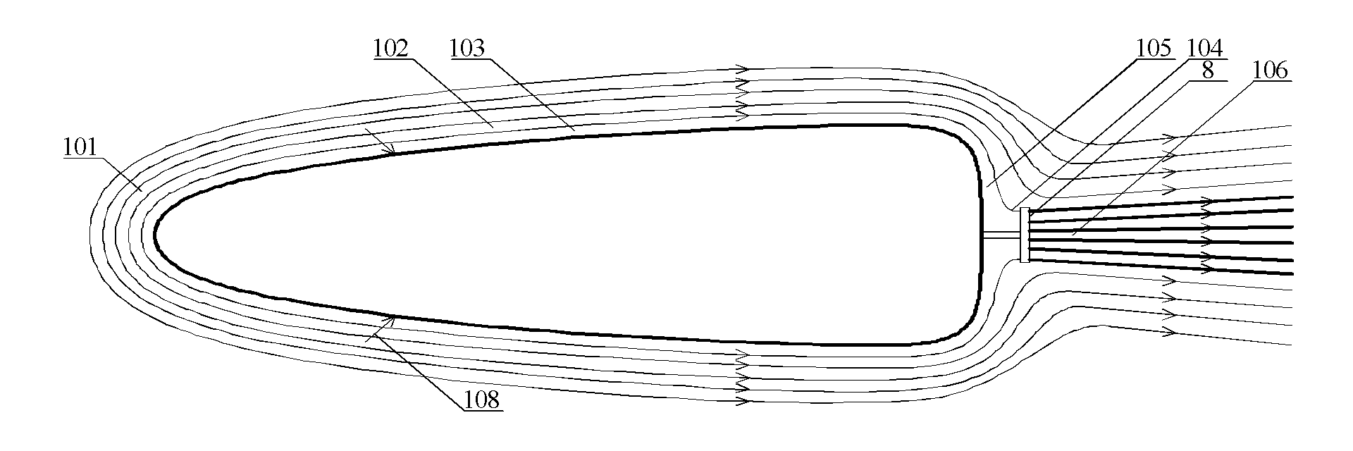
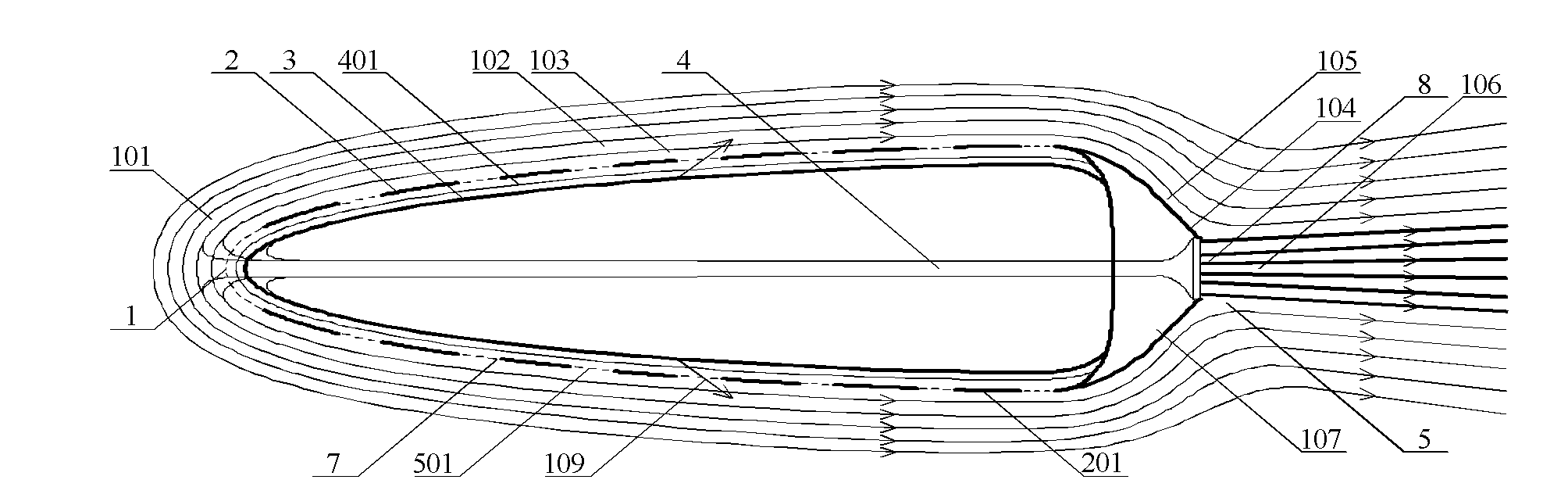
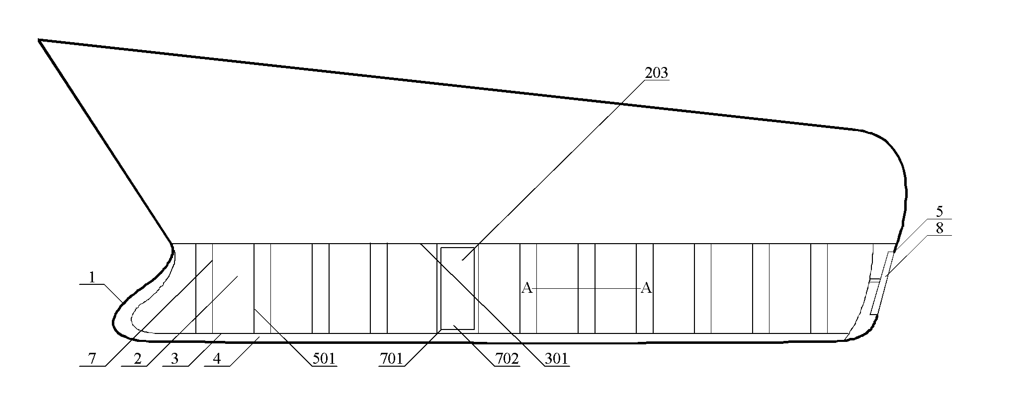
[0065] Example 1, such as Figure 2-6 As shown, the front end under the ship's waterline 301 is provided with a fluid inlet 1 with the same area as the fluid collision surface, which communicates with the tubular internal channel 4 and the fluid outlet 5 provided at the rear end, and a flow port 1 is provided at the rear under the ship's waterline. The shape of the linear guide body 107 can also be a semicircle, or a cone, or streamlined to facilitate the smooth flow of fluid without forming a small negative pressure zone. A fluid outlet 5 is provided at the intersection of the fluids in the middle of the guide body 107. It is convenient for the surrounding fluid to gather around the fluid outlet 5, and the propeller 8 is arranged in the fluid outlet 5, and the huge suction generated by the high-speed rotation of the propeller 8 can suck the fluid near the inlet 1 at a high speed, greatly reducing the resistance of the fluid wall, and conveniently The fluid is ejected at a hig...

Embodiment 2

[0071] Example 2, such as Figure 7-9 Shown, different from above-mentioned embodiment is that the fish scale is used as the spoiler, from the back of the ship forward and partially covered sequentially, the ship is under the waterline 301, and the scales on the shells on both sides are arranged the same as the scales on the body of the fish, evenly distributed with For the fish scale, the outer surface 201 of the fish scale is arc-shaped, and the inner surface 202 is plane. Between the inner surface 202 and the inner shell 3 is a fluid channel 401 .

[0072] When the ship is running fast, the fluid in the fluid channel 401 is already flowing, and the fluid is formed from the fish scales arranged with each other, and the arc-shaped peripheral edges of the unsealed outer surfaces 201 form a pressure inlet and outlet, and the fluid can be introduced there. Derived, a not wide fluid channel 401 is formed between the inner shell 3 and the flat inner surface 202 of the fish scales...

Embodiment 3

[0076] Example 3, such as image 3 , Figure 10-11 As shown, different from Embodiment 1, the internal passage 4 is located on the central axis of the part below the waterline of the hull, and a plurality of communicating through pipes 402 are provided between the shell of the ship and the internal passage 4, and the through pipes 402 communicates with the pressure inlet 703 of the casing. Of course, the through pipe 402 can be arranged between the hull of the bow of the ship and the internal channel 4 . The pressure inlets 703 to which these through pipes 402 are connected are located on both sides of the front of the ship where the forward fluid resistance is relatively large. A fluid channel 401 is formed between the outer shell and the inner shell 3 of the rear most part of the ship, and between a plurality of spoilers and the inner shell 3. The outer surface 201 of the spoiler is an arc surface, the inner surface 202 is a plane, and the rear propeller Change to suction...


PUM


Abstract

The invention discloses a navigation-hydraulic motor-driven device comprising an outer shell and a sealed inner shell. A fluid channel in a navigation direction is arranged between the outer shell and the inner shell; the outer shell is provided with a pressure lead-in port and a pressure lead-out port which are internally and externally communicated with each other; the fluid channel is respectively communicated with the pressure lead-in port and the pressure lead-out port on the outer shell; and a surface path of the outer surface of the outer shell in the navigation direction is longer than that of a fluid path in the fluid channel so that the flowing velocity of the fluid flowing through the surface path of the outer surface is faster than that in the fluid channel. The invention can improve the speed of the navigation-hydraulic motor-driven device with energy source conservation.

Description

technical field [0001] The invention relates to a mobile device, in particular to a water navigation mobile device. Background technique [0002] When ships and submarines are moving fast in the water, they are inevitably surrounded by thick fluids around them. Due to the long hulls of ships and submarines, the lateral force generates inward pressure of the fluid, which tightly wraps around and flows from head to tail, bringing The greater the friction, the faster the speed, the greater the pressure, the greater the friction, and the greater the fluid resistance. At present, streamlined shells are mostly used to reduce fluid resistance, but the effect is not obvious. [0003] When a ship or submarine is moving, its propulsion comes from the rear propeller. The water spraying side of the propeller generates a strong propulsion to push the ship to move fast. At the same time, the strong suction between its water-absorbing side and the rear shell , so that the negative pressu...

Claims


Application Information

Patent Timeline
Patent Type & Authority Applications(China)
IPC IPC(8): B63H5/00B63H5/07
Inventor 朱晓义
Owner 朱晓义
Why Eureka
Try Eureka