
Heavy oil hydroprocessing method and reactor

A treatment method, heavy oil hydrogenation technology, applied in the treatment of hydrocarbon oil, chemical instruments and methods, petroleum industry, etc., can solve the problem of failure to achieve conversion and desulfurization, demetallization, increased equipment investment and operating costs, high conversion rate and Impurity removal rate and other issues, to achieve high impurity removal rate and conversion rate, slow down the severity of the operation, and good raw material adaptability

Active Publication Date: 2013-08-28
CHINA PETROLEUM & CHEM CORP +1
View PDF3 Cites 0 Cited by
  • Summary
  • Abstract
  • Description
  • Claims
  • Application Information

AI Technical Summary

Problems solved by technology

[0005] There are following deficiencies in the ebullated bed reactor and process method of industrial application at present: because ebullated bed reactor is a kind of fully back-mixed reactor, a single reactor cannot reach higher conversion rate and impurity removal rate; and a kind of Generally, only one kind of catalyst is installed in the reactor, which fails to achieve the purpose of simultaneous conversion and desulfurization, demetallization and carbon removal
In order to improve this deficiency, literature (T.E Johnson etc., Oil&Gas J., July 1,1985, 50) increases the reactor of residual oil fluidized bed hydrocracking process from one to two or more, and in different reactors Different catalysts are filled inside. Although this improvement has improved the operation of the device, the operation is complicated and the equipment investment of the device is increased.
US4344840 and US4457829 introduced the combination process of ebullating bed and fixed bed hydrogenation to treat heavy hydrocarbon feedstock. This kind of combined process has improved the shortcomings of both ebullating bed and fixed bed processes, but the equipment investment and operating costs have increased significantly

Method used


Image

  • Heavy oil hydroprocessing method and reactor
  • Heavy oil hydroprocessing method and reactor
  • Heavy oil hydroprocessing method and reactor

Examples


Embodiment -1

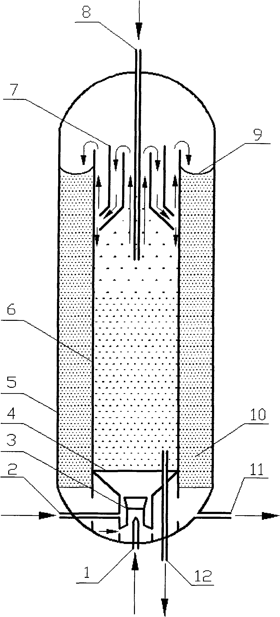
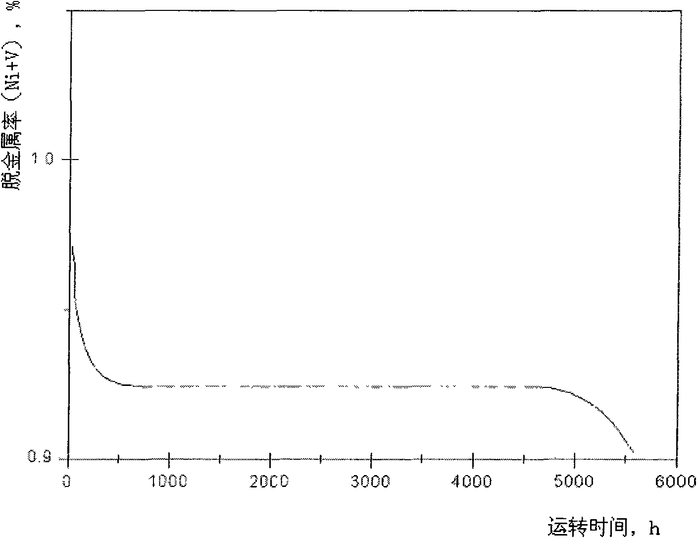
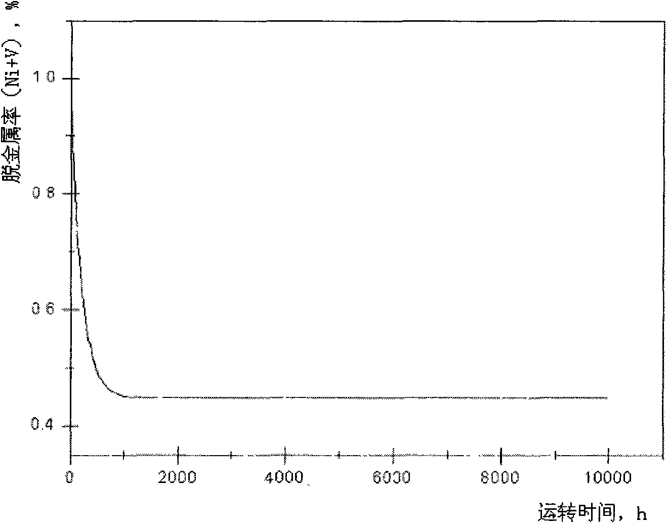
[0044] According to the present invention, experiments were carried out on a 60L medium-sized plant. The diameter of the reactor is 160mm, the diameter of the sleeve is 80mm, the total height of the reactor is 3500mm, and the height of the sleeve is 2800. The loading capacity of the ebullating bed catalyst is 6L, which is a demetallization catalyst, and the particle size of the catalyst is 0.2mm. The fixed bed catalyst loading capacity in the annulus is 42L, which is also a demetallization catalyst. The properties and reaction results of the raw oil used are shown in Table 1, and the results of long-term operation are shown in Table 1. image 3 .

[0045] Table 1

[0046] category

[0047] From the reaction results in Table 1 and Figure 2-4 It can be seen from the operation curve that under the same conditions of reaction temperature, reaction pressure and total space velocity, the demetallization rate of the fixed bed process in Comparative Example-1 is almost ...


PUM

PropertyMeasurementUnit
densityaaaaaaaaaa
diameteraaaaaaaaaa
specific surface areaaaaaaaaaaa

Abstract

The invention discloses a heavy oil hydroprocessing method and an internal loop reactor used by the method. In the heavy oil hydroprocessing method of the invention, the internal loop reactor is internally divided into two reaction segments, namely a fluidized bed reaction segment in a sleeve and a fixed bed reaction segment of a loop gap, and the mixture of heavy oil and hydrogen gas enters the reactor from the bottom and passes through the fluidized bed reaction segment first to undergo hydrogenation in the presence of a fluidized bed catalyst; and the catalyst is separated from the mixtureafter the reaction by a separator arranged on the upper part of the sleeve, and gas and liquid continuously go downwards to enter the fixed bed reaction segment of the loop gap to further undergo thehydrogenation in the presence of a fixed bed catalyst. The method has the combined characteristics of the fluidized bed and fixed bed hydrogenation processes, is well adapted to inferior raw materialoil with high metal and high asphaltene content and can realize the long-period stable operation of the device under the condition of achieving a high conversion rate and a high impurity removal rate.

Description

technical field [0001] The invention relates to a heavy oil hydrogenation treatment method and a reactor, in particular to a heavy oil hydrogenation treatment method combining ebullating bed reaction technology and fixed bed reaction technology and the used inner circulation reactor. Background technique [0002] According to the classification of reactor type, the hydrotreating process of heavy and low-quality feedstock oil can be divided into fixed bed, moving bed, ebullating bed and suspension bed. Among them, the fixed bed technology is relatively the most mature and has the most industrial applications. The simple flow of the process is: catalysts with different functions are packed in different reactors and different beds, and the raw oil and hydrogen are heated to the required temperature by the heating furnace, and then enter the reactor from the top of the reactor. The raw material oil and the hydrogen gas enter each catalyst bed in a co-current manner in a downflo...

Claims


Application Information

Patent Timeline
Patent Type & Authority Patents(China)
IPC IPC(8): C10G49/00B01J8/00
Inventor 杨涛方向晨胡长禄刘建锟葛海龙贾丽
Owner CHINA PETROLEUM & CHEM CORP
Learn More