
Eureka
For R&D, Eureka makes reading and utilizing patents & technical documents easy.
Eureka AIR
Designed for self-driven R&D workflows. Generate viable solutions, solve complex R&D challenges, empower your innovation with AI.

Eureka Materials
Designed for material experts only. Revolutionize your material R&D, from search, analyze, to developing new materials.

TechResearch
Generate reliable direction feasibility study reports for your R&D in just a few steps.

TechSeek
Discover and master advanced knowledge NOW. Basics, ideas, possibilities, all at once.

TechMind
As an expert in R&D Theories, TechMind can generates customized viable solutions instantly.

TechRisk
Analyze your overall solution with one click, know your potential R&D risks in advance.

TechMonitor
Get weekly tech updates, stay abreast of the latest tech innovations and key insights.
Air-conditioning refrigeration facility
A technology for air-conditioning refrigeration and equipment, applied in the field of multifunctional air-conditioning water heaters, can solve the problems of high temperature sensible heat waste of compressor exhaust, affecting normal use of hot water by users, unable to obtain hot water temperature, etc., and achieves low cost, simple structure, Reliable effect
- Summary
- Abstract
- Description
- Claims
- Application Information
AI Technical Summary
Problems solved by technology
Method used
Image


Examples
Embodiment 1
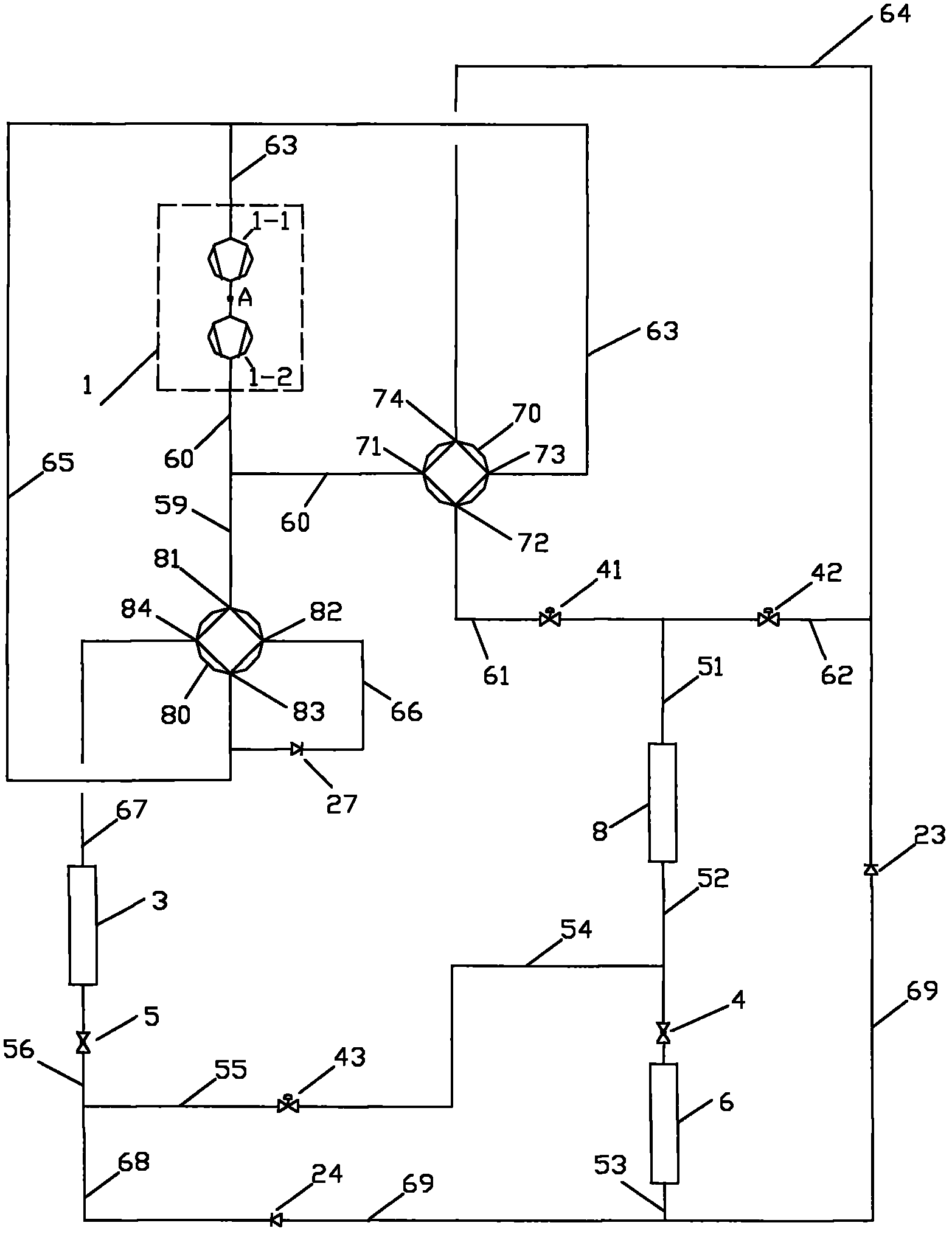
[0025] Such as figure 1 As shown, the present embodiment is an air-conditioning water heater, which is used in occasions with cooling, heating and hot water demands throughout the year. The whole equipment includes the following components: compression mechanism 1, first four-way valve 70, second four-way valve 80, first throttling mechanism 4, second throttling mechanism 5, user-side heat exchanger 3, heat source side heat exchanger device 6, heater 8, capillary 9, first flow control valve 41, second flow control valve 42, third flow control valve 43, third check valve 23 and fourth check valve 24; first throttling mechanism 4. The second throttling mechanism 5 , the first flow control valve 41 and the second flow control valve 42 are electronic expansion valves; the third flow control valve 43 is a solenoid valve.
[0026] The user-side heat exchanger 3 acts as an evaporator in summer to cool users, and in winter as a condenser to provide heating for users; The evaporator ...
Embodiment 2
[0059] Such as Figure 4 As shown, the present embodiment is also an air-conditioning water heater, which is used in occasions with cooling, heating and hot water demands throughout the year. The difference with Embodiment 1 is that a liquid reservoir 50 is added in the system, and its connection mode is: the second throttling mechanism 5 is connected with the liquid reservoir 50 through the fifty-sixth pipeline 56, and the outlet port of the fourth one-way valve 24 The sixty-eighth pipeline 68 is connected to the liquid reservoir 50, one end of the third flow direction control valve 43 is connected to the fifty-fourth pipeline 54, and the other end of the third flow direction control valve 43 is connected to the liquid reservoir 50 through the fifty-fifth pipeline 55. , the fifty-sixth pipeline 56 or any one of the sixty-eighth pipelines 68 is connected. Figure 4 As shown, the fifty-fifth pipeline 55 in this embodiment is connected to the liquid reservoir 50.
[0060] The ...
Embodiment 3
[0067] Such as Figure 5 As shown, the present embodiment is also an air-conditioning water heater, which is used in occasions that require cooling, heating and hot water throughout the year. The difference from Embodiment 1 is that a third throttling mechanism 7 is added to the system, and its connection mode is: one end of the third throttling mechanism 7 is connected to the heater 8, and the other end of the third throttling mechanism 7 passes through the fifty-second The pipeline 52 is connected with the first throttling mechanism 4 and the fifty-fourth pipeline 54 at the same time. Such as Figure 5 As shown, at this time, the first flow control valve 41 and the second flow control valve 42 can be replaced by the first one-way valve 21 and the second one-way valve 22 respectively.
[0068] Their connection mode is: the inlet port of the first check valve 21 is connected with the sixty-first pipeline 61, the outlet port of the first check valve 21 is connected with the h...
PUM
 Abstract
Description
Claims
Application Information
 - R&D Engineer
- R&D Manager
- IP Professional
- Industry Leading Data Capabilities
- Powerful AI technology
- Patent DNA Extraction
Browse by: Latest US Patents, China's latest patents, Technical Efficacy Thesaurus, Application Domain, Technology Topic, Popular Technical Reports.
© 2024 PatSnap. All rights reserved.Legal|Privacy policy|Modern Slavery Act Transparency Statement|Sitemap|About US| Contact US: help@patsnap.com