Backscatter-based distributed fiber-optic vibration system

A distributed optical fiber and backscattering technology, applied in the direction of using wave/particle radiation, measuring devices, instruments, etc., can solve the problems of long production cycle, high price, difficult maintenance, etc., and achieve the effect of reducing requirements

Active Publication Date: 2011-01-12
SHANGHAI BOOM FIBER SENSING TECH +1
View PDF3 Cites 10 Cited by
  • Summary
  • Abstract
  • Description
  • Claims
  • Application Information

AI Technical Summary

Problems solved by technology

As a result, this light source is expensive, has a long production cycle, and is difficult to maintain, and is not suitable for large-scale promotion

Method used


Image

  • Backscatter-based distributed fiber-optic vibration system
  • Backscatter-based distributed fiber-optic vibration system
  • Backscatter-based distributed fiber-optic vibration system

Examples


Embodiment Construction

[0014] Preferred embodiments of the present invention will be described in detail below in conjunction with the accompanying drawings.

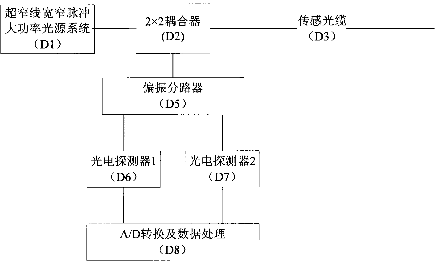
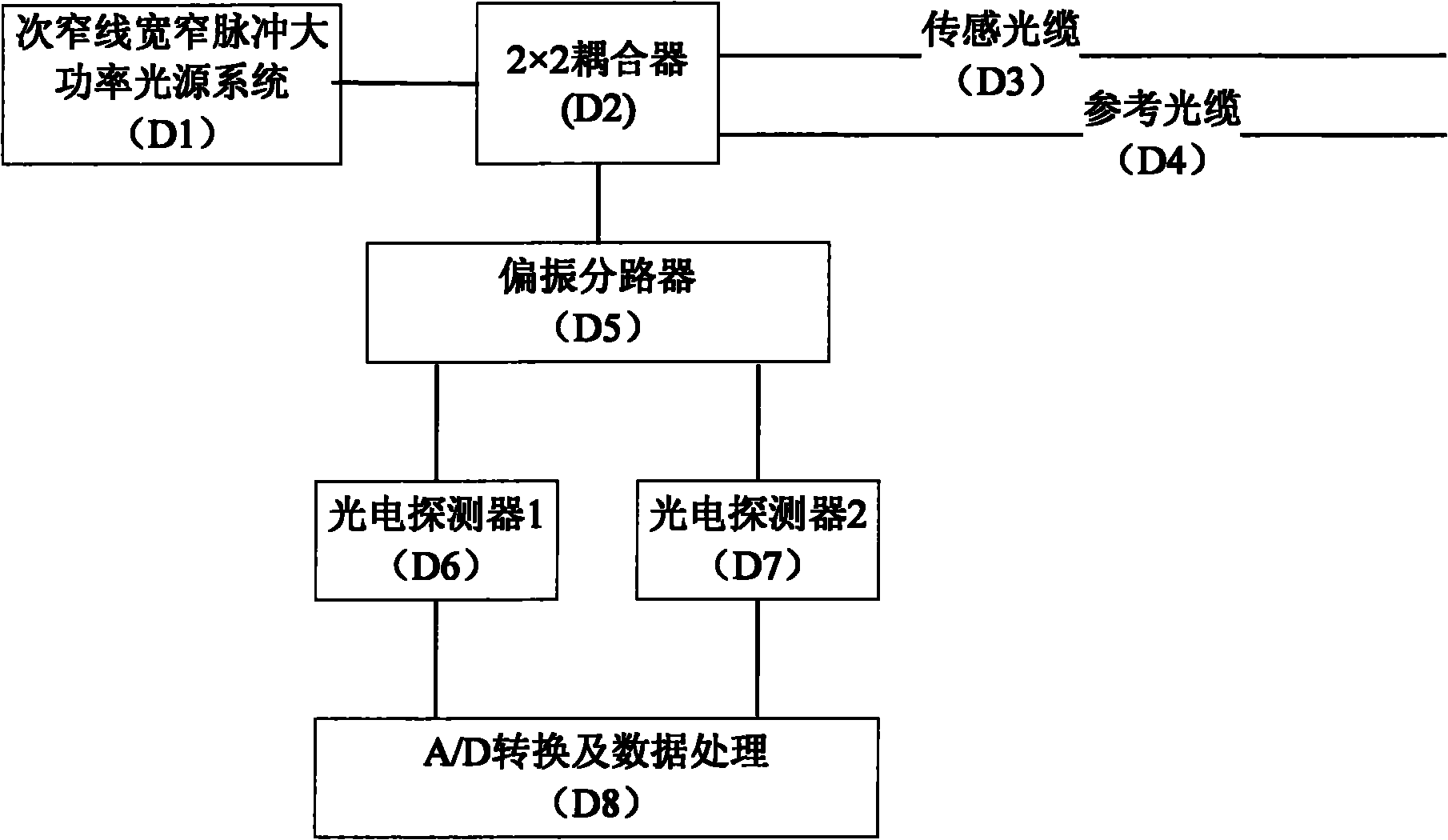
[0015] Please refer to Fig. 2, the present invention relates to a kind of distributed optical fiber vibration system based on backscattering, it comprises sub-narrow line width high-power pulse light source (D1), 2 * 2 coupler (D2), sensing optical cable (D3) and Reference optical cable (D4), polarization splitter (D5), photodetector 1 (D6) and photodetector 2 (D7), A / D converter and data processor (D8).

[0016] The output end of the sub-narrow linewidth high-power pulse light source (D1) is connected to the first port of the primary stage of the 2×2 coupler (D2), and the secondary stage of the 2×2 coupler (D2) is respectively connected to the sensing optical cable (D3) and the reference optical cable ( D4); the other port of the main stage of the coupler is connected to the polarization splitter (D5), and the output end of the polarization ...


PUM


Abstract

The traditional backscatter-base distributed fiber-optic vibration sensing technology (PDVS), as shown in chart 1, comprises a pulse light source 1; the traditional scheme only has one sensing optic cable (as shown in chart 1) and the interference actually occurs in the sensing optic cable. A backscatter-based distributed fiber-optic vibration sensing system comprises a light path system and a data processing system, wherein the light path system comprises a pulse light source, one end of which is connected with one end of a 2*2 coupler; the 2*2 coupler is connected with a sensing optic cableand a reference optic cable. According to the invention, the interference is transferred from the sensing optic cable to the coupler so as to limit the optic path difference of an interference signalin the technological error range of the coupler and reduce the requirement of the system for the line width of the light source.

Description

technical field [0001] The invention relates to the field of optical fiber vibration sensing, in particular to a distributed optical fiber vibration sensing system based on backscattering. Background technique [0002] Distributed optical fiber vibration sensing technology (PDVS) based on backscattering is an optical fiber sensing technology that can simultaneously achieve high positioning accuracy and high vibration feature recognition rate. [0003] The traditional distributed optical fiber vibration sensing technology (PDVS) based on backscattering is shown in Figure 1, which includes a pulsed light source 1, and the traditional solution has only one sensing optical cable (as shown in Figure 1), and the interference actually occurs at in the sensor cable. When the laser pulse is traveling, the scattered light generated by the front part and the scattered light generated by the rear part of the "catch up" laser pulse will overlap from a certain moment and interfere. From...

Claims


Application Information

Patent Timeline
Patent Type & Authority Applications(China)
IPC IPC(8): G01H9/00
Inventor 郭兆坤皋魏席刚周正仙仝芳轩
Owner SHANGHAI BOOM FIBER SENSING TECH
Why Eureka
Try Eureka