Reel-to-reel ultraviolet nanometer coining device and method
A nano-imprinting, roll-to-roll technology, used in optics, optomechanical equipment, instruments, etc., can solve the problems of low efficiency, limited deformation limit of copy effect, high cost, etc., to reduce production cost, increase flatness and hardness , Improve the effect of imprinting quality
- Summary
- Abstract
- Description
- Claims
- Application Information
AI Technical Summary
Problems solved by technology
Method used
Image

Examples
Embodiment 1
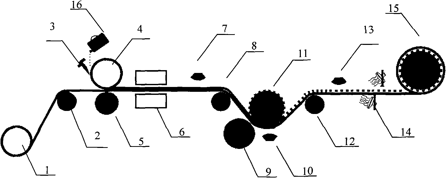
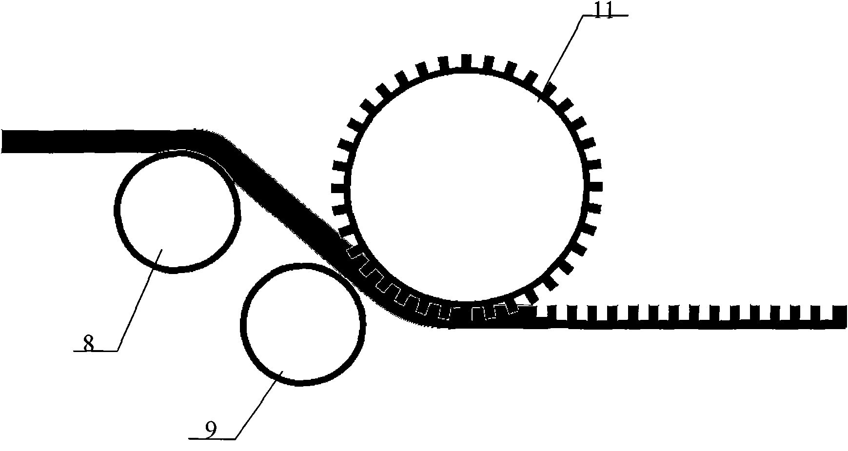
[0032] Embodiment one: see attached figure 1 as shown, figure 1 It is a roll-to-roll ultraviolet nanoimprinting device of the present invention, comprising: a transmission device, a coating device, a pre-curing device, an embossing device, a strong curing device and a cooling device.
[0033] Wherein the conveying device at least includes a discharge roller 1 and a take-up roller 15, which are located at both ends of the entire embossing device, and the cylindrical roll-up material to be embossed is placed on the discharge roller 1, and its open end is wound to The take-up roller 15, when the embossing is turned on, the unwinding roller 1 and the take-up roller 15 rotate at the same linear speed in the opposite direction of the material winding, so that the material to be embossed is transported along the specified route. The transmission device also includes auxiliary rollers 2, 8, and 12, which are respectively located on the entire transmission route, and these auxiliary r...
Embodiment 2
[0038] Embodiment two: embodiment two is on the basis of embodiment one, on discharge roller 1 and receiving roller 15, two rectification systems before and after are set, as Figure 5 As shown, the deviation correction system includes a material edge sensor and a transmission repair device. The material edge sensor can be an infrared sensing device 17, and the conveying and repairing device is provided with an axial displacement device 18 on the discharging roller 1 and the receiving roller 15, and the two are electrically connected. When the infrared sensing device 17 senses that the material is shifted inward during the conveying process, the axial displacement device 18 controls the discharging roller 1 or the receiving roller 15 to move inward, otherwise the displacement occurs outward. The two deviation correction systems make the front and rear displacement errors within 30um during the transmission of the imprinted materials, thus eliminating the need for alignment ste...
Embodiment 3
[0039] Embodiment 3: Embodiment 3 is based on Embodiment 1 or Embodiment 2, and further includes a tension control system, which is arranged on any number of rollers that play a role in transmission, such as Figure 6 shown. The tension control system is mainly composed of a tension sensing device 19 and a magnetic powder clutch device 20. When the tension sensing device 19 finds that the tension is greater than a preset value during material transmission, the magnetic powder clutch device 20 slightly reduces the winding speed. At the preset value, the magnetic powder clutch device 20 slightly increases the winding speed. The predetermined value may be the deformation rating of the material or other value that may affect the surface tension of the material. Through the tension control system, it is ensured that the material is always in a state of tension during the embossing process, avoiding the generation of waste products caused by wrinkles, and improving the production y...
PUM
| Property | Measurement | Unit |
|---|---|---|
| Thickness | aaaaa | aaaaa |
Abstract
Description
Claims
Application Information
 - Generate Ideas
- Intellectual Property
- Life Sciences
- Materials
- Tech Scout
- Unparalleled Data Quality
- Higher Quality Content
- 60% Fewer Hallucinations
Browse by: Latest US Patents, China's latest patents, Technical Efficacy Thesaurus, Application Domain, Technology Topic, Popular Technical Reports.
© 2025 PatSnap. All rights reserved.Legal|Privacy policy|Modern Slavery Act Transparency Statement|Sitemap|About US| Contact US: help@patsnap.com