Recovery-type harmonic suppression system at DC side of multi-pulse rectification system and method

A multi-pulse rectification and harmonic suppression technology, which is applied to output power conversion devices, electrical components, etc., can solve the problems of increased volume and capacity, and achieve the effects of increased volume, large system capacity and simple structure.

Active Publication Date: 2011-01-12
HARBIN INST OF TECH
View PDF3 Cites 17 Cited by
  • Summary
  • Abstract
  • Description
  • Claims
  • Application Information

AI Technical Summary

Problems solved by technology

[0005] The purpose of the present invention is to solve the problem that the existing multi-pulse rectification system uses an active filter for harmonic compensation on the AC side, which increases the volume and capacity of the system, and provides a DC side of the multi-pulse rectification system Recycling Harmonic Suppression System and Method

Method used


Image

  • Recovery-type harmonic suppression system at DC side of multi-pulse rectification system and method
  • Recovery-type harmonic suppression system at DC side of multi-pulse rectification system and method
  • Recovery-type harmonic suppression system at DC side of multi-pulse rectification system and method

Examples


specific Embodiment approach 1

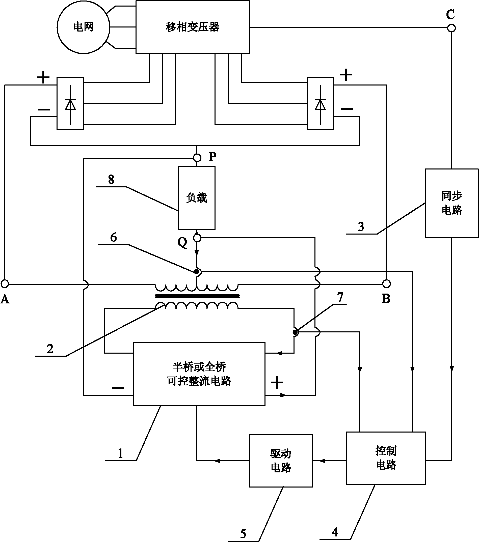
[0024] Specific implementation mode one: the following combination figure 1 Describe this embodiment, the DC side recovery type harmonic suppression system of the multi-pulse rectification system described in this embodiment, it includes a half-bridge or full-bridge controllable rectification circuit 1, a balance reactor with a secondary side 2, a synchronous circuit 3. Control circuit 4, drive circuit 5, load loop current sensor 6 and reactor secondary current sensor 7,

[0025] The primary side of the balanced reactor 2 with the secondary side is connected between the power input terminal A and the power input terminal B of the harmonic suppression system, and the middle tap of the primary side of the balanced reactor 2 with the secondary side is connected to the harmonic The positive output terminal Q of the load power supply of the suppression system, the secondary side of the balance reactor 2 with the secondary side is connected to the AC input terminal of the half-bridg...

specific Embodiment approach 2

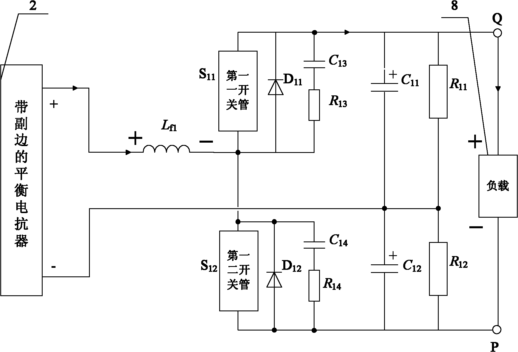
[0032] Specific implementation mode two: the following combination figure 1 and figure 2This embodiment is described. This embodiment is a further limitation of Embodiment 1. The half-bridge or full-bridge controllable rectification circuit 1 is a half-bridge controllable rectification circuit, and the half-bridge controllable rectification circuit is composed of a first inductor L f1 , the first switch tube S 11 , the first diode D 11 , the first and third capacitors C 13 , the first and third resistors R 13 , the first capacitor C 11 , the first resistor R 11 , the first and second switching tube S 12 , the first and second diode D 12 , the first four capacitance C 14 , the first and fourth resistors R 14 , the first and second capacitance C 12 and the first two resistors R 12 composition,

[0033] The positive pole of the secondary side of the balance reactor 2 with the secondary side is connected to the first inductance L f1 At one end, the first inductor L ...

specific Embodiment approach 3

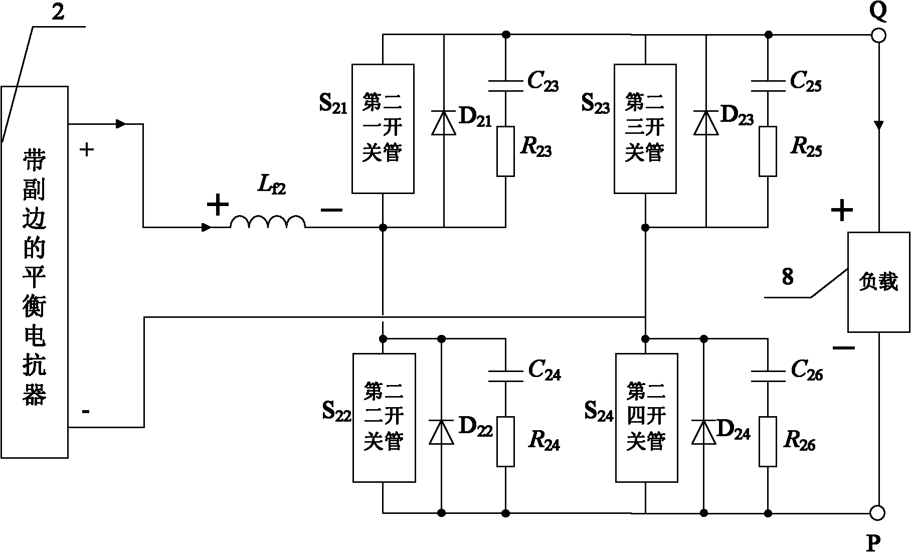
[0039] Specific implementation mode three: the following combination figure 1 with image 3 Describe this embodiment, this embodiment is a further limitation of Embodiment 1, the half-bridge or full-bridge controllable rectification circuit 1 is a full-bridge controllable rectification circuit, and the full-bridge controllable rectification circuit is composed of a second inductor L f2 , the second switch tube S 21 , the second one diode D 21 , the second and third capacitance C 23 , the second and third resistors R 23 , the second and third switching tubes S 23 , the second and third diodes D 23 , the second five capacitance C 25 , the second fifth resistance R 25 , the second switch tube S 22 , the second two diode D 22 , the second and fourth capacitance C 24 , the second and fourth resistance R 24 , the second and fourth switching tubes S 24 , the second and fourth diode D 24 , the second six capacitance C 26 and the second six resistors R 26 composition,

...


PUM


Abstract

The invention relates to a recovery-type harmonic suppression system at the DC side of a multi-pulse rectification system and a method, belonging to the technical field of power electronics and solving the problems of system size and capacity increase of a traditional multi-pulse rectification system which adopts an active filter at the AC side for harmonic suppression. The invention is used for connecting the harmonic suppression system to the DC side of an original multi-pulse rectification system by utilizing the relation of current harmonics at the AC side and the DC side aiming at a parallel multi-pulse rectification system. The harmonic energy of the original parallel multi-pulse rectification system is extracted through the secondary side of a balance reactor with the secondary side to generate a small-capacity power supply source to influence the current of the AC side and suppress the current harmonics at the DC side, wherein the current harmonics are input at the AC side. The secondary current is rectified through a half-bridge or full-bridge controllable rectification circuit connected with the secondary side of the balance reactor with the secondary side, and the rectified output current is directly provided to a load to recycle the harmonic energy. The invention is used for the harmonic suppression of the multi-pulse rectification system.

Description

technical field [0001] The invention relates to a DC-side recycling harmonic suppression system and method of a multi-pulse rectification system, belonging to the technical field of power electronics. Background technique [0002] As a common high-power electric energy conversion system, the multi-pulse rectification system has been widely used in the industrial field. The time-varying and non-linear characteristics of this kind of rectification system will cause it to generate a large number of harmonics, thereby reducing the power factor of the system, and causing consequences such as AC voltage distortion. At present, the multi-pulse rectification system has become the main power grid main source of harmonics. [0003] Generally speaking, there are two basic ideas to solve the problem of harmonic pollution in the multi-pulse rectification system in the prior art. One is remedial measures, which compensate the harmonics generated by the rectification system by installing ...

Claims


Application Information

Patent Timeline
Patent Type & Authority Applications(China)
IPC IPC(8): H02M1/14
Inventor 杨世彦孟凡刚杨威朱屹
Owner HARBIN INST OF TECH
Why Eureka
Try Eureka