Multiplexing delay unit circuit

A delay unit and circuit technology, applied in the direction of electrical components, automatic power control, etc., can solve the problems of large area and power consumption, limited output frequency adjustment range, fixed delay unit stages, etc., to achieve area and power consumption Reduce, reduce design overhead, and expand the effect of frequency adjustment range

Inactive Publication Date: 2011-01-12
NAT UNIV OF DEFENSE TECH
View PDF3 Cites 5 Cited by
  • Summary
  • Abstract
  • Description
  • Claims
  • Application Information

AI Technical Summary

Problems solved by technology

[0008]1. A ring oscillator consisting of a conventional delay unit (e.g. Figure 1), the number of delay unit stages is fixed, and the output frequency can only be adjusted by changing the control voltage, and the adjustment range of the output frequency is limited;
[0009]2. A variable gain oscillator formed by changing the number of delay units (such as Figure 2), the output frequency can be adjuste

Method used


Image

  • Multiplexing delay unit circuit
  • Multiplexing delay unit circuit
  • Multiplexing delay unit circuit

Examples


Embodiment Construction

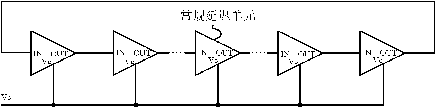
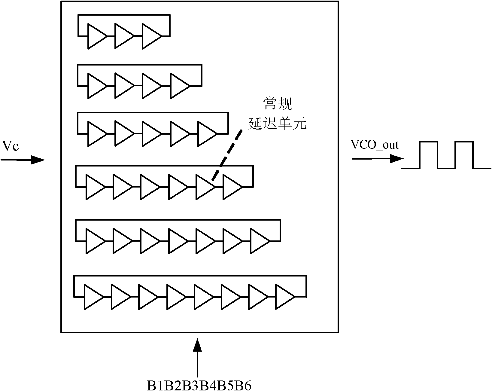
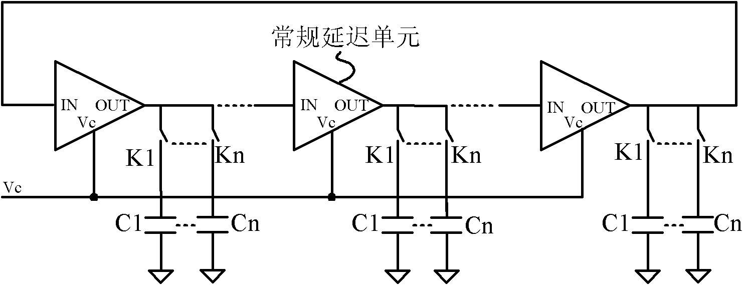
[0028] like Figure 4 As shown, the present invention is a reusable delay unit, which includes two parts, an analog switch circuit and a conventional delay unit. The analog switch circuit is composed of a first analog switch K1 and a second analog switch K2, the first input signal IN1 is connected to the first analog switch K1, the second input signal IN2 is connected to the second analog switch K2, the first analog switch K1 and the second analog switch The other ends of the switch K2 are connected together and commonly connected to the signal input end of the delay unit. When the first analog switch K1 is closed and the second analog switch K2 is open, the first input signal IN1 is input to the delay unit circuit by the analog switch K1; when the first analog switch K1 is open and the second analog switch K2 is closed, The second input signal IN2 is input into the delay unit circuit by the analog switch K2. The invention realizes the expansion of the input signal of the de...


PUM


Abstract

The invention discloses a multiplexing delay unit circuit, and aims to implement a delay unit circuit with multiplexing function, implement a loop oscillator of different delay unit stages with as low design overhead as possible and acquire multiple oscillator gains. The invention adopts the technical scheme that: the signal input end of a delay unit is connected with an analog switch circuit; and the analog switch circuit consists of a first analog switch K1 and a second analog switch K2, wherein the K1 is connected with a first input signal IN1 under the control of a first control signal C1, the K2 is connected with a second input signal IN2 under the control of a second control signal C2, and the other ends of the K1 and the K2 are connected with the signal input end of the delay unit. The multiplexing delay unit circuit can receive two paths of input; and an oscillator consisting of the multiplexing delay unit circuit can provide multiple gains, and the area and the power consumption overhead of the oscillator are greatly reduced compared with a conventional variable gain oscillator.

Description

[0001] technical field [0002] The invention belongs to the field of integrated circuit design and is applied to a delay unit circuit of a ring oscillator, in particular to a reusable delay unit circuit. Background technique [0003] Ring oscillators are widely used in various integrated circuits. The range of frequency tuning and the speed of frequency tuning are important parameters to measure the performance of the ring oscillator. With the advancement of electronic manufacturing technology and the improvement of people's requirements for the operating frequency and response speed of integrated circuits, ring oscillators that can achieve a wide frequency tuning range and multiple gains are increasingly favored by the industry. Therefore, the ring oscillator with multiple gains and wide frequency tuning range is the development trend of today's oscillator technology and has a great application prospect. [0004] figure 1 A multistage ring oscillator based on a conventi...

Claims


Application Information

Patent Timeline
IPC IPC(8): H03L7/06
Inventor 郭阳赵振宇张均安陈书明孙永节刘衡竹陈吉华马卓梁斌刘必慰池雅庆刘祥远唐涛王丽萍欧阳玺段志奎曾斌杨方杰
Owner NAT UNIV OF DEFENSE TECH
Why Eureka
Try Eureka